Full variable valve engine and control method thereof

An engine and valve mechanism technology, applied in engine components, combustion engines, machines/engines, etc., can solve problems such as easy misfire, low combustion temperature, and difficulty in ignition, and achieve long service life, low noise, and low impact vibration. Effect

Active Publication Date: 2014-09-03
长城汽车股份有限公司平湖分公司
View PDF4 Cites 17 Cited by
  • Summary
  • Abstract
  • Description
  • Claims
  • Application Information

AI Technical Summary

Problems solved by technology

However, CAI combustion mode is prone to misfires when the engine is started, especially at low temperature and cold start, and it is difficult to ignite due to its low combustion temperature.
And when the engine is under low load, CAI combustion will also cause excessive carbon monoxide and hydrocarbon emissions due to the incomplete oxidation of carbon monoxide during the combustion process due to the lower combustion temperature, and it will also be caused by almost all fuels when the engine is under heavy load. Simultaneous combustion and heat release can easily cause knocking

Method used


Image

  • Full variable valve engine and control method thereof
  • Full variable valve engine and control method thereof
  • Full variable valve engine and control method thereof

Examples


Embodiment 1

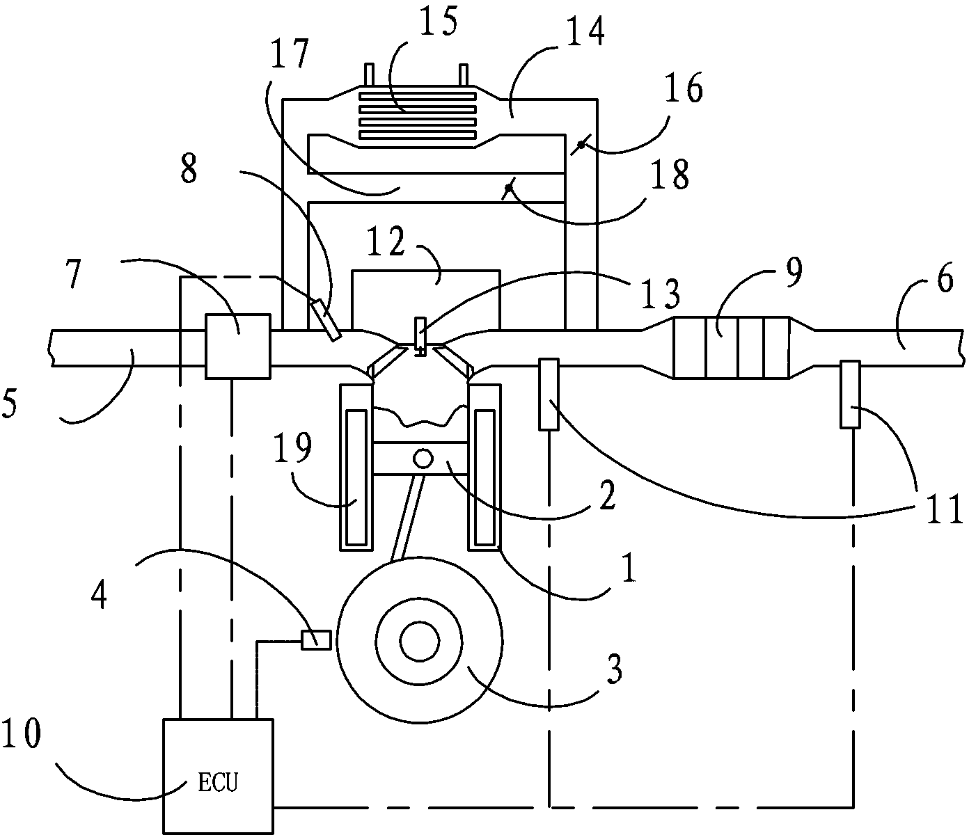
[0033] This embodiment relates to a fully variable valve engine, which uses a mixture of gasoline and ethanol as fuel, such as figure 1 As shown in , it includes a cylinder 1, a piston 2 is arranged in the cylinder 1, and a crank connecting rod mechanism 3 is connected to the lower end of the piston 2. The upper part of the cylinder 1 is communicated with an intake passage 5 and an exhaust passage 6 , a throttle valve 7 is arranged on the intake passage 5 , and a fuel injector 8 is also arranged downstream of the throttle valve 7 in the intake passage 5 . An exhaust gas treatment unit 9 is arranged on the exhaust passage 6 , and the exhaust gas treatment unit 9 can be a conventional three-way catalytic converter for treating the exhaust gas discharged from the cylinder 1 . Oxygen sensors 11 are respectively arranged on both sides of the exhaust gas treatment unit 9 in the exhaust passage 6 for detecting exhaust gas so as to regulate engine operation. A spark plug 13 is arrang...

Embodiment 2

[0043] This embodiment relates to a control method of a fully variable valve engine, and the fully variable valve engine has the structure of the fully variable valve engine in the first embodiment above. The control method of this fully variable valve engine comprises the steps described below, and its overall process can be as follows Figure 4 shown in .

[0044] When the engine is started, especially when the engine is started at a low temperature, because the temperature in the engine cylinder 1 is low, it is not conducive to the compression ignition in the CAI mode, so at this time the SI combustion mode ignited via the spark plug 13 can be used, that is, the mode One, in order to realize the smooth ignition and warm-up of the engine. At this time, the ignition timing of spark plug 13 is controlled by ECU10, and the intake valve and exhaust valve in the fully variable valve train on intake port 5 and exhaust port 6 can be fixed timing opening and closing under the contr...


PUM


Abstract

The invention relates to a full variable valve engine which comprises an air cylinder with an air inlet channel and an exhaust channel. A piston is arranged in the air cylinder. The bottom end of the piston is connected with a crank-link mechanism. A sparking plug is arranged in the air cylinder. A throttle valve and an oil sprayer are arranged on the air inlet channel. A tail gas processing unit is arranged on the exhaust channel. Full variable valve mechanisms are arranged at the communication portions of the air inlet channel, the exhaust channel and the air cylinder. An EGR channel with a cooler is arranged between the air inlet channel and the exhaust channel in a connecting mode. An EGR valve is arranged on the EGR channel. The engine further comprises an ECU control unit which can control the spark plug, the oil sprayer, the EGR valve and the full variable valve structures to make the engine operate. The invention further relates to a full variable valve engine control method. The shortcoming of an existing electric control hydraulic and electric control magnetic force driving mode can be overcome, the engine can be controlled to operate under various combustion modes, and the fuel economy and the emission performance of the engine are further improved.

Description

technical field [0001] The invention relates to an automobile engine technology, in particular to a fully variable valve engine. The present invention also relates to a control method of the above-mentioned fully variable valve engine. Background technique [0002] With the continuous development of automobile engine technology, in order to improve the fuel economy of the engine and reduce the emission of harmful substances from the engine, fully variable valve technology and controllable nature (CAI) have become the research fields of various automobile companies. At present, the technologies for realizing the fully variable control of the valve mechanism include electronically controlled hydraulically driven valve mechanism, electrically controlled magnetically driven valve mechanism and electronically controlled pneumatically driven valve mechanism. These valve trains can realize the characteristics of variable valve opening phase, closing phase and lift in a wide range ...

Claims


Application Information

Patent Timeline
Patent Type & Authority Applications(China)
IPC IPC(8): F01L1/34F02M25/07F02M26/01F02M26/13
CPCY02T10/121Y02T10/12
Inventor 高锋军潘旭陈亚青齐雪飞李东海
Owner 长城汽车股份有限公司平湖分公司
Why Eureka
Try Eureka