
Gas coal hydrofracture field time-space monitoring device and method

A hydraulic fracturing and monitoring device technology, applied in the direction of material resistance, etc., can solve the problems of increased construction cost, inability to realize the comprehensive evolution of coal and rock mass structure, continuous evaluation of time and space, and impact on coal mine safety production, etc., to achieve low production cost, Good airtightness and simple structure

Inactive Publication Date: 2014-09-03
CHINA UNIV OF MINING & TECH
View PDF3 Cites 26 Cited by
  • Summary
  • Abstract
  • Description
  • Claims
  • Application Information

AI Technical Summary

Problems solved by technology

[0004] However, the current evaluation of the effect of hydraulic fracturing only stays in very traditional means, such as examining the traditional indicators such as drilling cuttings and water content and examining the effect of gas drainage.
These parameters are all "point evaluation" of the potential impact area of ​​hydraulic fracturing, that is, by taking cores from fixed locations in the potential impact area of ​​hydraulic fracturing to test the relevant parameters and then evaluate whether hydraulic fracturing affects this point, it is impossible Achieving a comprehensive and continuous spatiotemporal evaluation of the evolution of the coal and rock mass structure in the area will inevitably lead to blindness in effect inspection and later gas drainage construction, which will not only affect the safe production of coal mines, but also lead to a substantial increase in construction costs

Method used


Image

  • Gas coal hydrofracture field time-space monitoring device and method
  • Gas coal hydrofracture field time-space monitoring device and method

Examples


Embodiment Construction

[0039] An embodiment of the present invention will be further described below in conjunction with accompanying drawing:

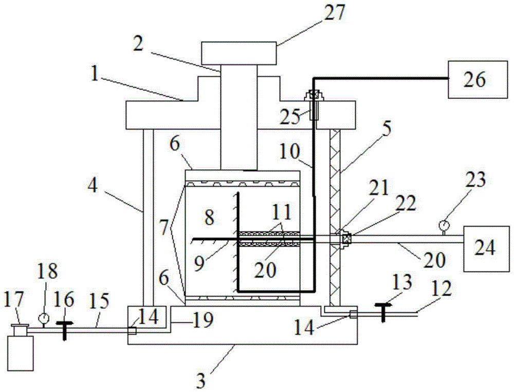
[0040] like figure 1 As shown, the gas-coal hydraulic fracturing fracture field space-time monitoring device of the present invention is composed of a main cavity, an in-situ stress simulation module, a gas filling and discharging module, a hydraulic fracturing module and a resistivity testing module. The main cavity includes a base 3, a square cylinder disposed on the base 3 and an upper cover 1 disposed on the square cylinder. The front, rear and left sides of the square cylinder are observable hydraulic fracturing surfaces. The plexiglass 4 of the real-time fracture evolution process on the surface of the coal sample 8, the right side is the steel plate 5 with the guide hole 21, the base 3 is provided with a left channel and a right channel leading to the cylinder body, and the left channel and the right channel entrance There are sealing bolts 14 respe...


PUM


Abstract

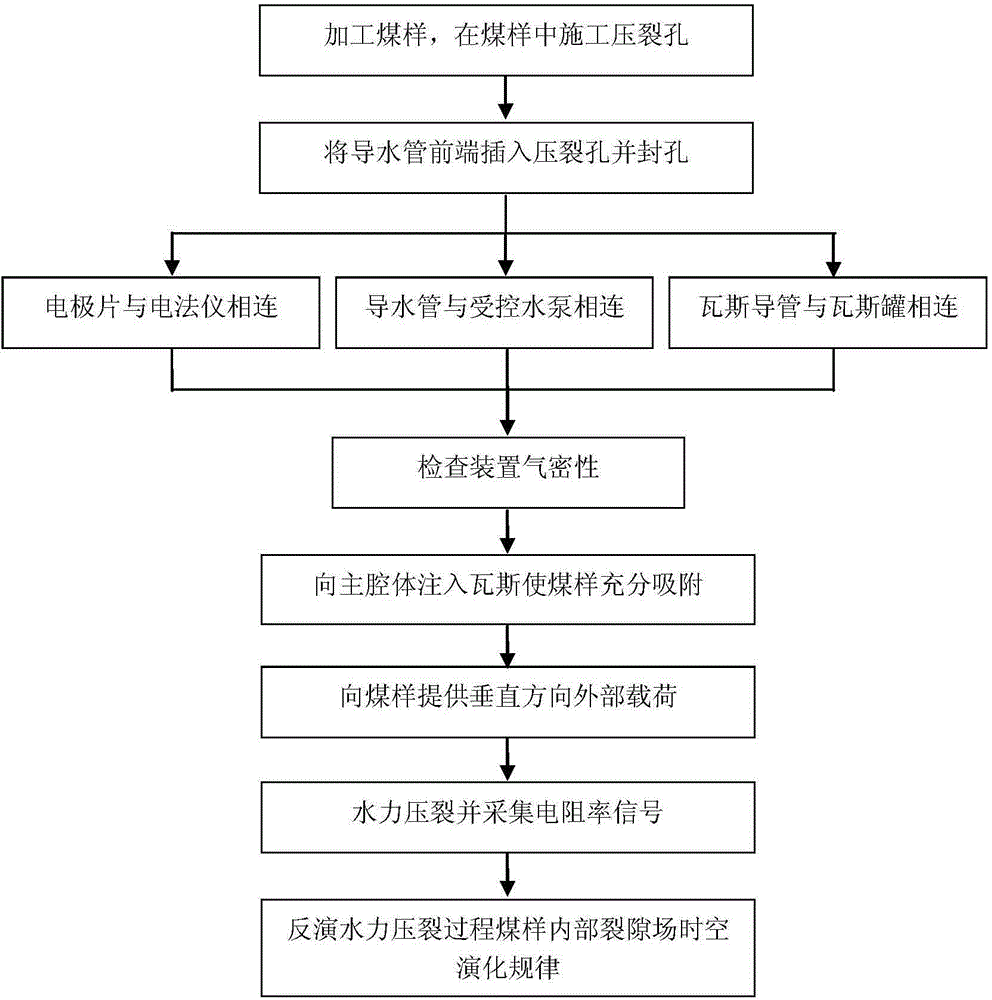
The invention discloses a gas coal hydrofracture field time-space monitoring device and method. The device comprises a main cavity body, a crustal stress simulation module, a gas charging and discharging module, a hydrofracture module and a resistivity testing module which are arranged on the main cavity body, wherein the crustal stress simulation module is used for simulating the stress state of a coal body under a filed condition; the gas charging and discharging module is used for charging gas into a coal body; the hydrofracture module is used for providing pressure water for the coal body; the resistivity testing module is used for testing resistivity signals in a hydrofracture process of a coal sample. A coal sample obtained at the field is put into the main cavity body of the device, and gas is charged into the main cavity body, so that the coal sample adsorbs the gas fully, and external load is applied; high-pressure salt water is injected into preset drill holes in the coal sample and the preset drill holes are fractured; meanwhile the resistivity variation in the coal sample in the process is tested; the distribution in a three-dimensional space and the time-space evolution process of a fracture of the coal body are monitored continuously by the sensitive response to the salt water by resistivity. Additionally, the device also can determine the reasonable water injection pressure of the coal sample under different conditions.

Description

technical field [0001] The invention relates to a time-space monitoring device and method for gas coal hydraulic fracturing fissure field, which belongs to the field of coal mine gas disaster prevention and coal mine safety technology, and is especially suitable for measuring the effective action area of ​​hydraulic fracturing anti-permeability measures in gas-containing coal. and methods. Background technique [0002] my country is rich in coal resources, but the occurrence conditions of coal seams vary greatly. There are many gas-containing coal seams and large gas reserves. High gas and coal and gas outburst mines account for more than 50% of the total number of mines. But with the efficient intensification of coal production and the increase of mine mining depth, the amount of gas gushing out is increasing, and the threat of coal and gas outburst and gas explosion is becoming more and more serious. Gas disasters have become the most important factor restricting the safe...

Claims


Application Information

Patent Timeline
IPC IPC(8): G01N27/04
Inventor 宋大钊王恩元王勃邱黎明黄兰英
Owner CHINA UNIV OF MINING & TECH
Learn More