Supercharge Your Innovation With Domain-Expert AI Agents!

Novel laminated busbar

A laminated busbar, a new type of technology, applied in the direction of coupling devices, electrical components, connections, etc., can solve the problems that the technical solution cannot be realized, cannot withstand the current of the medium power drive circuit, and cannot weld the laminated busbar, etc., and achieves a simple structure , high reliability, low cost effect

Active Publication Date: 2014-09-03
SUZHOU WEST DEANE MACHINERY
View PDF10 Cites 40 Cited by
  • Summary
  • Abstract
  • Description
  • Claims
  • Application Information

AI Technical Summary

Problems solved by technology

[0005]2. High-power drive circuit above 100KW: the control device uses high-power IGBT modules, the substrate uses laminated busbars, and the high-power IGBT modules are fixedly connected to the stack by bolts. Layer busbar, the drive circuit has large control current, simple circuit structure, high reliability, but expensive, typical applications such as rail transit, ship drive, smart grid, etc.;
[0007]For medium power drive circuits, from the point of view of design principles, multiple IGBT chips or MOS tubes can be driven in parallel to reduce the The cost of the medium-power drive circuit, but the existing PCB board cannot withstand the current of the medium-power drive circuit, and the IGBT chip or MOS tube cannot be welded to the existing laminated busbar, making this technical solution impossible

Method used


Image

  • Novel laminated busbar
  • Novel laminated busbar
  • Novel laminated busbar

Examples


Embodiment 1

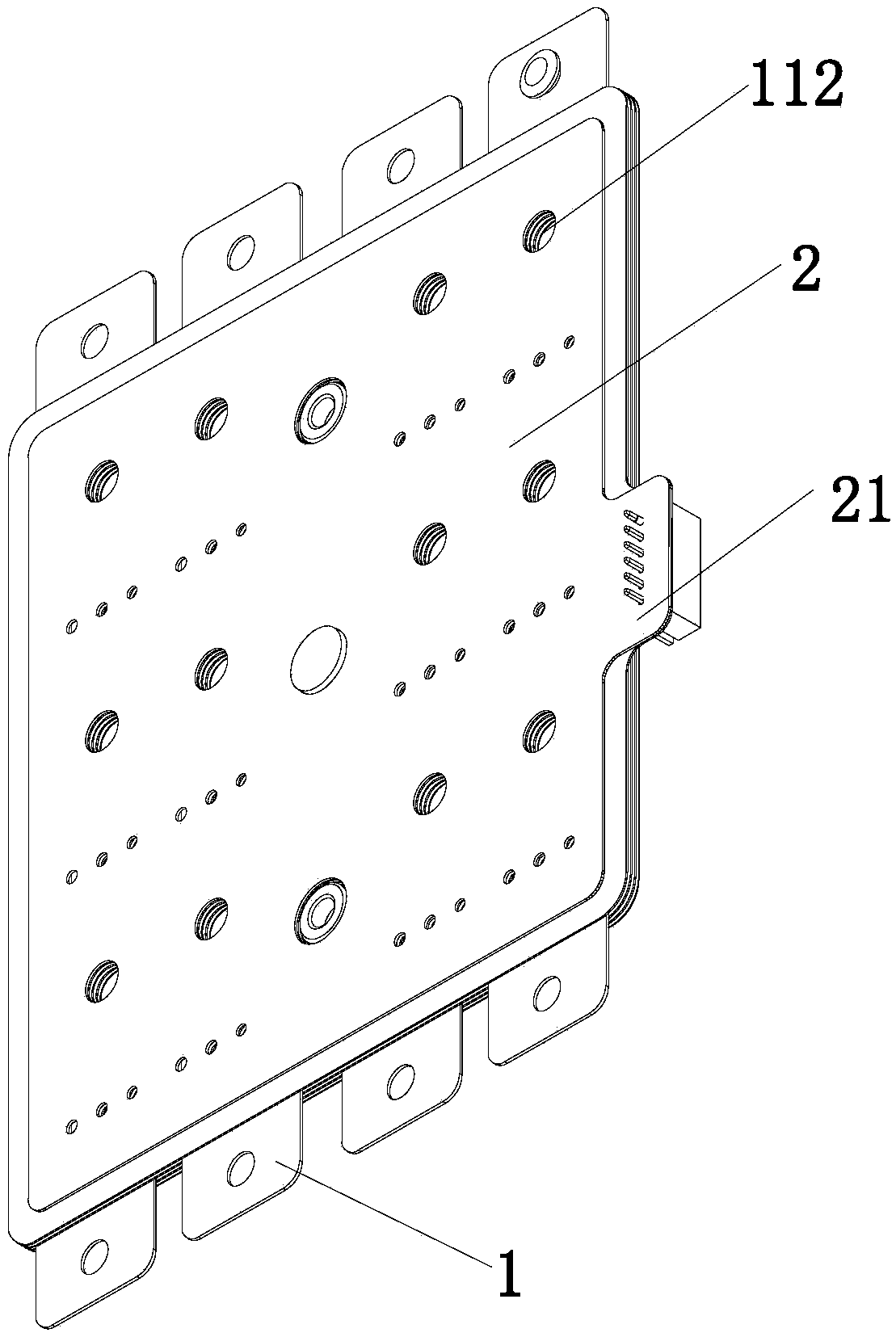
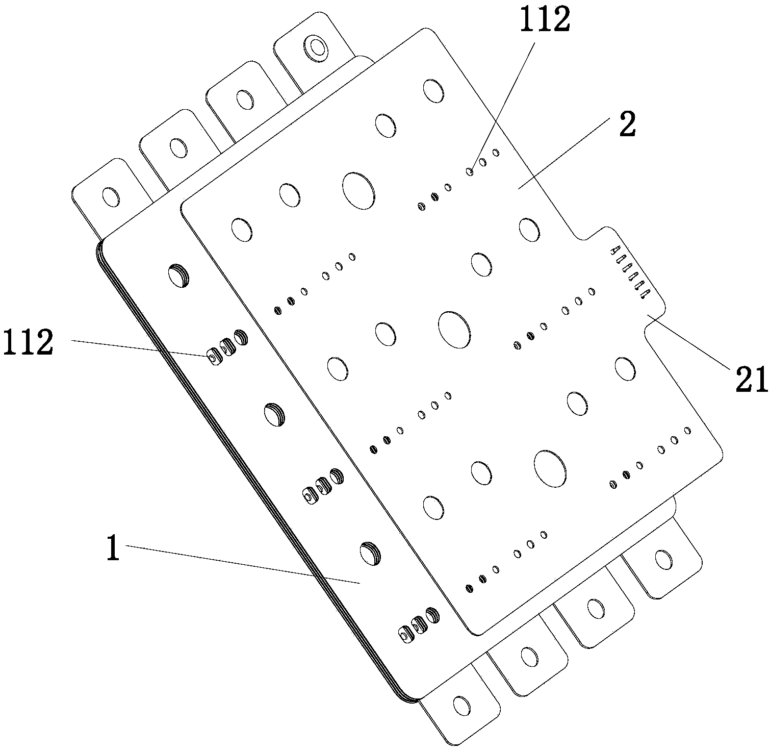
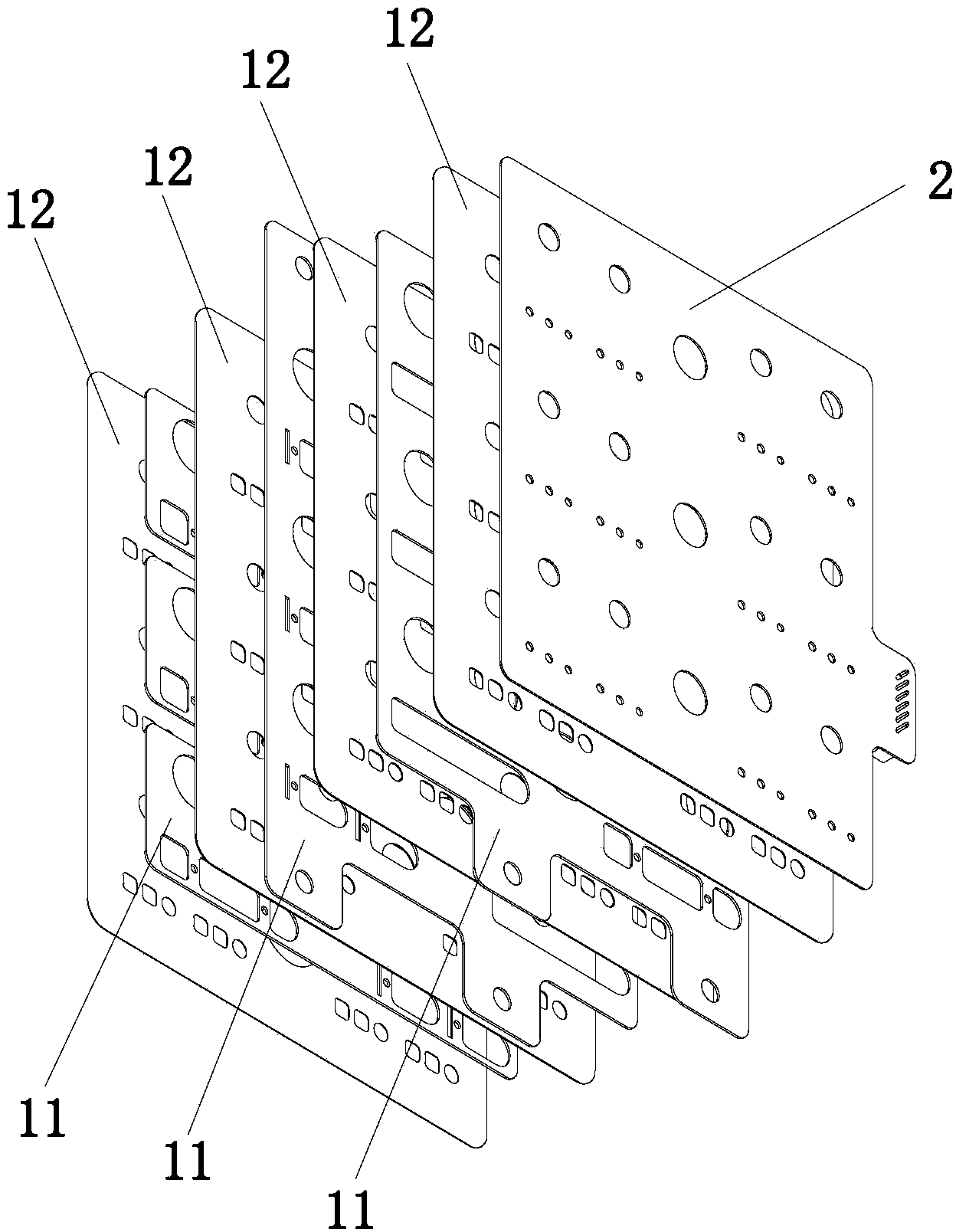
[0044] as attached Figure 5 The structure front view of the specific application embodiment of the present invention and the appended Figure 8 As shown in the top view of the specific application embodiment of the structure of the present invention, the heat sink 4 in the figure is not connected to the IGBT chip 3, so as to describe the technology of the present invention in detail, and does not represent the final connection state of the present invention. A new type of laminated busbar, which includes a laminated busbar body 1 composed of a multi-layer conductive layer 11 and a multi-layer insulating layer. The insulating layer is composed of an insulating film 12. The surface of the laminated busbar body 1 is bonded with Twelve IGBT chips 3 are installed on the PCB board 2 , the laminated busbar body 1 and the mounting holes 112 on the PCB board 2 , and a radiator 4 is connected to and installed on the IGBT chip 3 . The IGBT chip 3 is welded to the laminated busbar body ...

Embodiment 2

[0047] The difference between this embodiment and Embodiment 1 is: the diameter of the welding hole 113 is 1.8 mm, the width of the strip 111 is also 1.8 mm, and the width of the strip 111 is 0 mm larger than the diameter of the welding hole 113 .

Embodiment 3

[0049] The difference between this embodiment and Embodiment 1 is: the diameter of the welding hole 113 is 1.8 mm, the width of the strip 111 is 2.3 mm, and the width of the strip 111 is 0.5 mm larger than the diameter of the welding hole 113 .


PUM


Abstract

A novel laminated busbar comprises a laminated busbar body formed by multilayered conducting layers and multilayered insulating layers. A PCB is adhered to the surface of the laminated busbar body. The PCB is adhered to the surface of the laminated busbar body through a press-fit mode. The PCB can be adhered to the upper surface of the laminated busbar body and also can be adhered to the lower surface of the laminated busbar body. During production and processing, an insulating film having viscosity at double faces is arranged between the PCB and the laminated busbar body, and the PCB and the laminated busbar body are pressed as a whole through a press. According to the invention, mounting holes in the conducting layers in the laminated busbar body that need to be welded with components are set as oblong shapes, and the oblong shapes are provided with welding holes such that components can be welded on the laminated busbar. Thus, direct welding between an IGBT chip or MOS tube and the laminated busbar is realized; a novel medium-power drive circuit is realized; and costs of the medium-power drive circuit are greatly reduced.

Description

technical field [0001] The invention relates to a medium-power drive system, in particular to a laminated busbar for medium-power drive systems such as electric vehicles, wind power generation, medium-power frequency converters, and medium-power inverters. [0002] Background technique [0003] It is a composite fully-controlled voltage-driven semiconductor device composed of BJT and MOS. It has the characteristics of fast switching speed, low conduction voltage, low driving power, high operating frequency, and flexible control. Therefore, it is widely used in modern power electronics technology. in the power control circuit. The existing power drive circuits are mainly divided into low-power drive circuits below 10KW, high-power drive circuits above 100KW, and medium-power drive circuits between 10KW and 100KW. The main features are as follows: [0004] 1. Low-power drive circuit below 10KW: the control chip uses IGBT chips or MOS tubes, the substrate uses PCB boards, and...

Claims


Application Information

Patent Timeline
IPC IPC(8): H01R25/16
Inventor 盛建华
Owner SUZHOU WEST DEANE MACHINERY
Features
  • R&D
  • Intellectual Property
  • Life Sciences
  • Materials
  • Tech Scout
  • Unparalleled Data Quality
  • Higher Quality Content
  • 60% Fewer Hallucinations
Learn More