Movable charging vehicle

A mobile charging and charging machine technology, applied in the field of vehicles, can solve the problems of increasing construction costs, being unable to continue driving, wasting electric energy, etc., and achieve the effect of improving charging efficiency and shortening charging time

Inactive Publication Date: 2014-09-03
OPTIMUM BATTERY CO LTD
View PDF5 Cites 31 Cited by
  • Summary
  • Abstract
  • Description
  • Claims
  • Application Information

AI Technical Summary

Problems solved by technology

Household or bus electric vehicles have brought great convenience to people. At the same time, a prominent problem has arisen. Electric vehicles often fail to continue because they do not reach the charging station and the power stored in the power battery is exhausted. driving
At present, the number of charging stations is small and built in relatively remote locations. Drivers usually need to drive a long distance to reach the charging station, wasting electricity
And if the electric energy has been exhausted before arriving at the charging station, it is generally costly and inconvenient to ask a tow truck to tow the electric vehicle to the charging station, and the towing process may also cause damage to the electric vehicle
Charging stations are generally built in remote places. Buses go to the charging station for charging, which wastes energy. The charging station is not perfect, which limits the popularity of new energy buses. If a large number of charging stations are built, it will waste land and increase Construction cost; in addition, the time of charging at the charging station cannot be selected. If charging is encountered during the peak power consumption during the day, the cost of electricity price will be higher

Method used


Image

  • Movable charging vehicle
  • Movable charging vehicle

Examples


Embodiment Construction

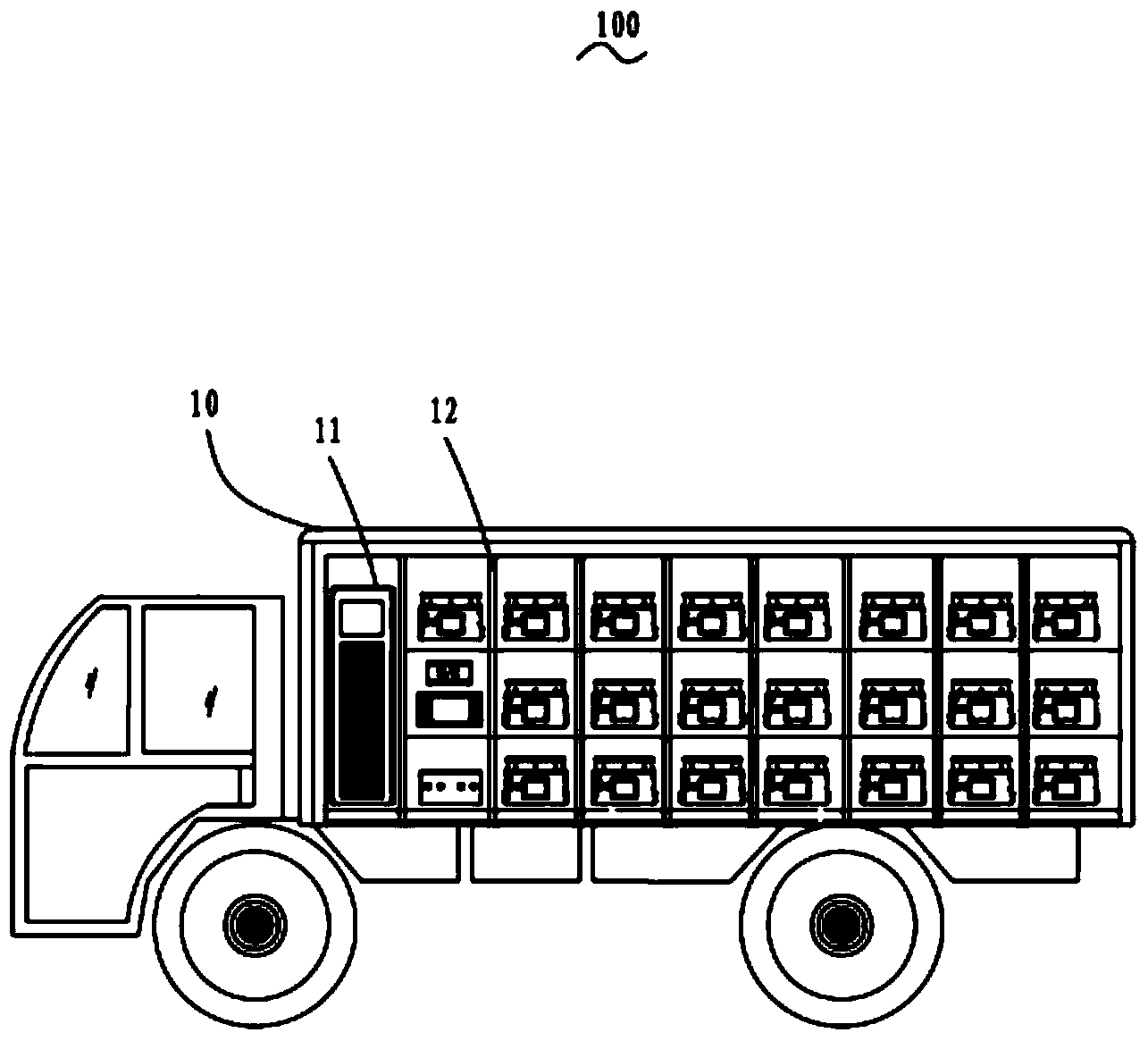
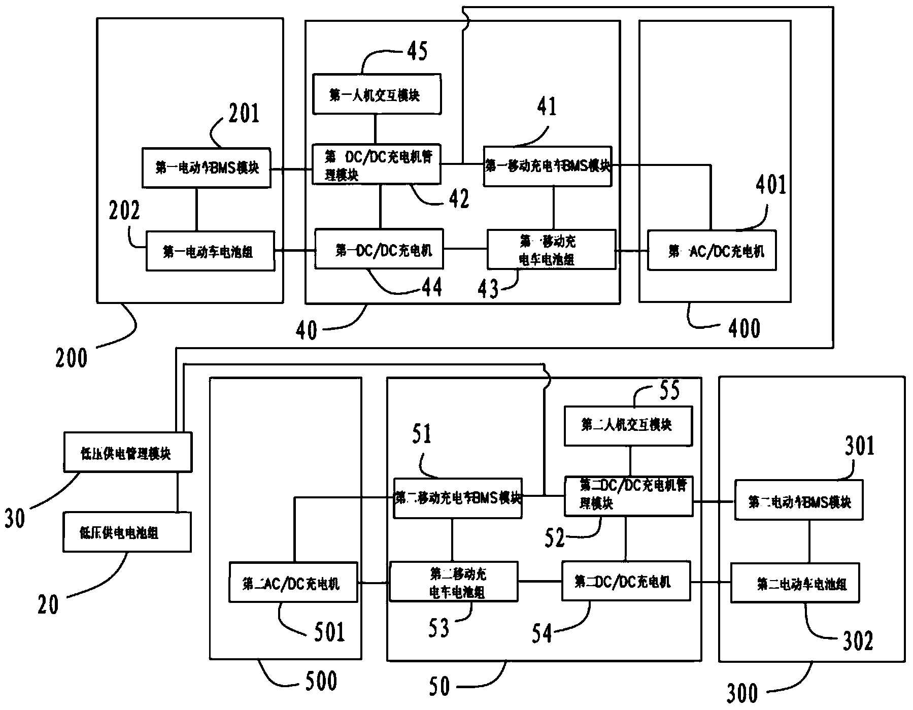
[0013] see figure 1 and figure 2 , a mobile charging vehicle 100 provided by the present invention is used to charge one or two electric vehicles at the same time. In this embodiment, the electric vehicle may be, for example, an electric bus and / or an electric car, figure 2 It is shown that the mobile charging vehicle 100 simultaneously charges two electric vehicles, that is, the first electric vehicle 200 and the second electric vehicle 300 . The mobile charging vehicle 100 includes a carriage 10 , a low-voltage power supply battery pack 20 , a low-voltage power supply management module 30 , a first charging system 40 and a second charging system 50 disposed in the carriage 10 .

[0014] Specifically, the first charging system 40 includes a first mobile charging vehicle BMS (battery management system, battery management system) module 41, a first DC / DC charger management module 42 connected to the first mobile charging vehicle BMS module 41 And the first mobile charging ...


PUM


Abstract

A movable charging vehicle comprises a carriage, a low-voltage power supply battery pack, a low-voltage power supply management module, a first charging system and a second charging system, wherein the low-voltage power supply battery pack, the low-voltage power supply management module, the first charging system and the second charging system are arranged in the carriage. The first charging system comprises a first movable charging vehicle BMS module, a first movable charging vehicle battery pack, a first DC/DC charging machine management module, a first DC/DC charging machine and a first man-machine interaction module. The second charging system comprises a second movable charging vehicle BMS module, a second movable charging vehicle battery pack, a second DC/DC charging machine management module, a second DC/DC charging machine and a second man-machine interaction module. The first movable charging vehicle battery pack is used for charging a first electric vehicle through the first DC/DC charging machine, and the second movable charging vehicle battery pack is used for charging a second electric vehicle through the second DC/DC charging machine. The first movable charging vehicle battery pack and the second movable charging vehicle battery pack can charge the first electric vehicle or the second electric vehicle at the same time through the corresponding DC/DC charging machines.

Description

technical field [0001] The invention relates to the field of vehicles, and more specifically relates to a mobile charging vehicle for charging electric vehicles anytime and anywhere. Background technique [0002] At present, the energy of traditional fuel vehicles mainly depends on oil, and the shortage of oil and the serious environmental pollution caused by the tail gas emitted by fuel vehicles have made it more and more urgent for human beings to research new green vehicles. As a green transportation tool, electric vehicles not only have remarkable energy-saving effects, but also greatly improve the comprehensive utilization rate of energy, zero exhaust emissions, and obvious environmental benefits. With the continuous improvement of the rechargeable battery manufacturing process, electric vehicles will have the strength to compete with traditional fuel vehicles in the not-too-distant future. Household or bus electric vehicles have brought great convenience to people. At...

Claims


Application Information

Patent Timeline
Patent Type & Authority Applications(China)
IPC IPC(8): H02J7/00
Inventor 李瑶
Owner OPTIMUM BATTERY CO LTD
Why Eureka
Try Eureka