
Linear type electro-hydraulic

An electro-hydraulic pump, linear technology, applied in the direction of pump, pump control, piston pump, etc., can solve the problems of aggravating energy friction loss, high production cost and operating cost, and wide variation range, and achieves improved efficiency and energy utilization. , the effect of high energy utilization efficiency and a wide range of applications

Inactive Publication Date: 2014-09-03
QINGDAO UNIV
View PDF4 Cites 1 Cited by
  • Summary
  • Abstract
  • Description
  • Claims
  • Application Information

AI Technical Summary

Problems solved by technology

[0002] At present, on construction vehicles, the working mode of the engine-driven hydraulic system is often used, and there are some difficult problems in this working mode
Due to the wide range of power demand changes of engineering vehicles, it directly leads to the waste of engine energy and the deterioration of emissions. The energy generated during the work process cannot be effectively recovered, and the changes in engine work and load cannot be adapted to each other.
Although the piston-type internal combustion engine-driven hydraulic system can convert heat energy into multi-channel hydraulic energy, but because there are two sets of crank-link mechanisms in the system, the lateral force of the piston and plunger caused by the swing of the two connecting rods is relatively large, which not only aggravates the frictional loss of energy, and bring severe wear and additional heat load between the piston and the cylinder wall, plunger and cylinder wall; in addition, the crank-connecting rod mechanism has a high stress strength, and the joints are still relatively large when the joints are fully lubricated. Friction loss; the unevenness of system operation is large; the most serious is that the energy of the system passes through multiple intermediate conversion and transmission links, with low efficiency, complex and heavy structure, high production cost and operation cost, and serious pollution, etc.

Method used


Image

  • Linear type electro-hydraulic

Examples


Embodiment

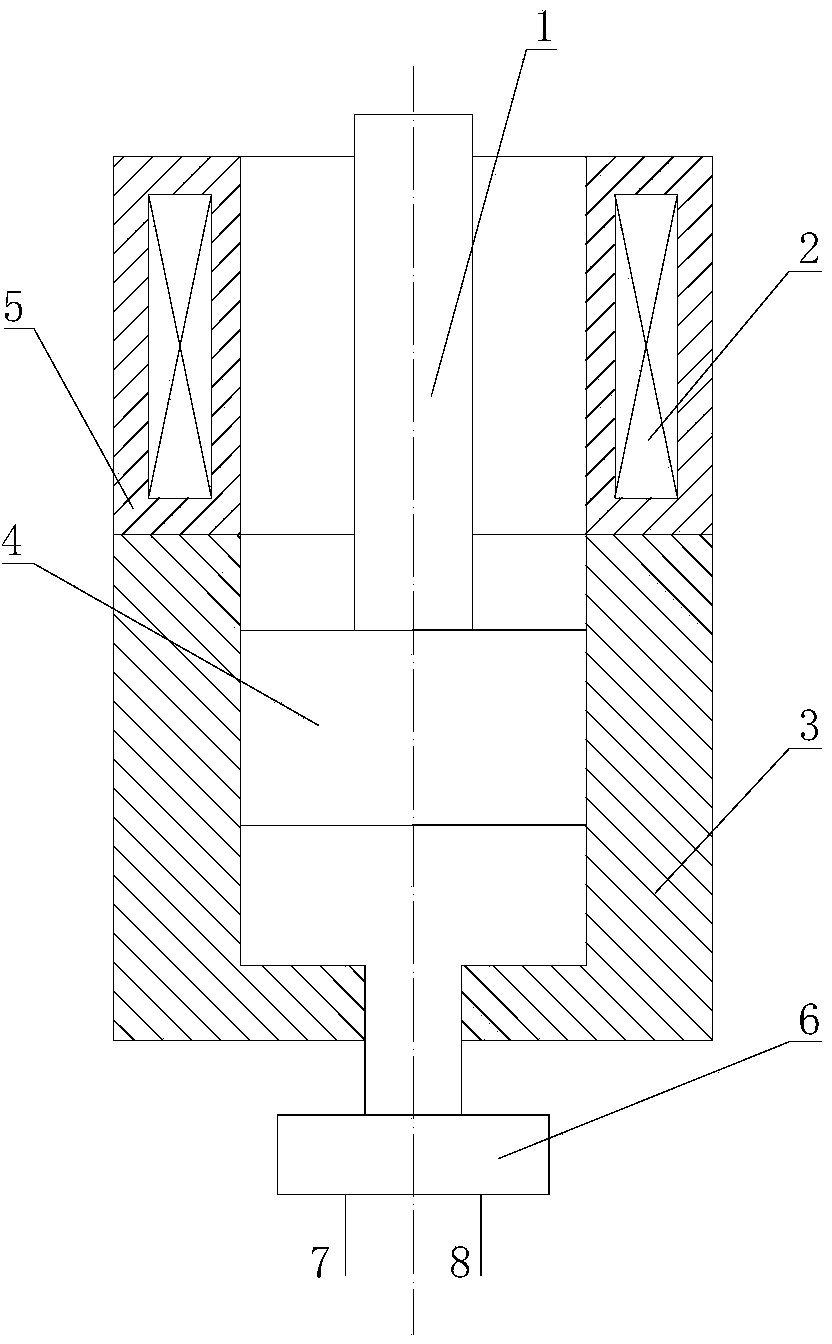
[0011] The main structure of this embodiment includes a mover 1, an electromagnetic coil 2, a cylinder body 3, a plunger 4, a stator 5, a flow distribution system 6, an inlet pipe 7 and an outlet pipe 8; the electromagnetic coil 2 is wound with insulated wires The cylinder body 3 is made of cast iron, alloy cast iron or aluminum alloy according to the needs; the cylinder body 3 is provided with a plunger 4, the mover 1 and the plunger 4 are solidly connected as one, the stator 5 and the cylinder body 4 are solidly connected as one, The stator 5 is provided with an electromagnetic coil 2; the bottom of the cylinder body 3 is provided with a flow distribution system 6, and the bottom of the flow distribution system 6 is provided with an inlet pipe 7 and an outlet pipe 8; the relative linear motion between the stator 5 and the mover 1, the plunger 4 Simultaneously make relative linear motion with the cylinder body 3; the number of plunger 4 is determined according to specific cond...


PUM


Abstract

The invention belongs to the technical field of combination of electric power and hydraulic pressure, and relates to a linear type electro-hydraulic. An electromagnetic coil is formed by winding an insulated conductor. A cylinder body is made of cast iron or alloy cast iron or aluminum alloy according to the demand. A plunger piston is arranged in the cylinder body, a rotor is fixedly connected with the plunger piston into a whole, a stator is fixedly connected with the cylinder body into a whole, and the electromagnetic coil is arranged in the stator. The bottom of the cylinder body is provided with a current distribution system, and an inlet pipe and an outlet pipe are symmetrically arranged at the bottom of the current distribution system. The stator and the rotor do relative linear movement, and the plunger piston and the cylinder body do relative linear movement. The number of plunger pistons is determined according to the specific situation. The linear type electro-hydraulic is simple in structure, scientific in principle, convenient to operate, safe in use, high in energy utilization efficiency, wide in application range, low in discharging value and friendly to the environment.

Description

Technical field: [0001] The invention belongs to the technical field of combining electric power and hydraulic pressure, and relates to a brand-new equipment for converting electric energy into hydraulic energy or hydraulic energy into electric energy, especially a linear electro-hydraulic pump system, which is suitable for vehicles, engineering machinery and oil drilling machinery In the process, the excess hydraulic energy is recovered and converted into electrical energy storage. Background technique: [0002] At present, on engineering vehicles, the working mode of the engine-driven hydraulic system is often used, and there are some difficult problems in this working mode. Due to the wide range of power demand changes of engineering vehicles, it directly leads to the waste of engine energy and the deterioration of emissions. The energy generated during the work process cannot be effectively recovered, and the change of engine work and load cannot be adapted to each other...

Claims


Application Information

Patent Timeline
Patent Type & Authority Applications(China)
IPC IPC(8): H02K33/00H02K35/02F04B17/04F04B9/103F04B49/12
Inventor 张铁柱赵红尹怀先马永志程联军华青松张洪信
Owner QINGDAO UNIV
Learn More