Automatic coating apparatus

An automatic coating and coating technology, which is applied in the direction of spraying devices, devices for coating liquid on the surface, and processing devices for used abrasives, which can solve problems such as excessive exposure of operators

Active Publication Date: 2014-09-03
DOOSAN HEAVY IND & CONSTR CO LTD
View PDF5 Cites 1 Cited by
  • Summary
  • Abstract
  • Description
  • Claims
  • Application Information

AI Technical Summary

Problems solved by technology

However, nuclear reactor flanges are the most heavily contaminated areas with high doses of radiation, so there is a problem of operator overexposure to radiation

Method used


Image

  • Automatic coating apparatus
  • Automatic coating apparatus
  • Automatic coating apparatus

Examples


Embodiment Construction

[0025] The automatic coating device according to the present invention will now be described in detail with reference to the accompanying drawings. For the simple description of the specification, the suffix "module" or "part" of the components used in the following description is considered to be only granted or specially mixed and distinguished, and has no meaning or function in itself. As implemented in this specification, similar to the same reference numerals are given to the same and similar embodiments with different configurations. As used herein, unless the context clearly uses otherwise, singular expressions include plural meanings.

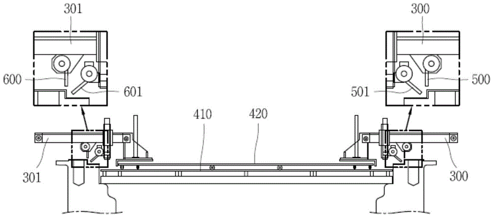
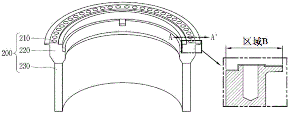
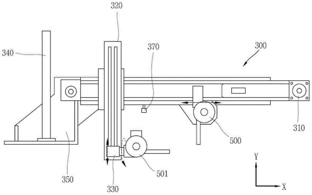
[0026] The present invention provides an automatic coating device, which is applied to the flange of the atomic reactor in the atomic power station to remove the corrosion film of the flange and then coat the flange so that no re-corrosion occurs. The automatic coating device is configured for remote control so that it can be operated in ...


PUM

PropertyMeasurementUnit
particle sizeaaaaaaaaaa

Abstract

The present invention relates to an automatic coating apparatus which coats a cylindrical flange to prevent corrosion. The automatic coating apparatus includes: a rail mounted on a flange; a first body configured to rotate along the rail, and having at least one axial joint configured to rotate or to move in a straight line; a coating module disposed on one end of the axial joint, and including a coating gun configured to coat the flange; and a control part controlling the rotation of the first body, the movement of the axial joint, and the operation of the coating gun.

Description

Technical field [0001] The present invention relates to an automatic coating device for coating the surface of a flange included in a nozzle or pipe connection structure in a nuclear power plant. Background technique [0002] The nuclear reactor flange used in nuclear power generation is exposed to a high temperature environment of 350°C during its operation. During the planned maintenance period, the nuclear reactor flange was exposed to a solution of boric acid as the main coolant at room temperature for about 8 days. [0003] Because the nuclear reactor flange is made of carbon steel, surface corrosion will occur when the nuclear reactor flange is exposed to the environment. If corrosion occurs, red corrosion products will be generated. Due to the long-term operation of the nuclear reactor flange, the red corrosion products will fall off and form foreign substances. Foreign matter penetrates into the nuclear reactor, so there will be problems in the safety of nuclear power gen...

Claims


Application Information

Patent Timeline
Patent Type & Authority Applications(China)
IPC IPC(8): G21C21/00B05C19/00G21C1/00
CPCY02E30/40Y02E30/30B05B13/04B24C3/06B24C9/00C23C24/06
Inventor 朴光洙朴光容
Owner DOOSAN HEAVY IND & CONSTR CO LTD
Why Eureka
Try Eureka