
Evaporator for treating oily sewage

An evaporator and oily sewage technology, applied in the field of water treatment, can solve the problems of high equipment installation accuracy, difficult to clean the dirt layer, and reduce heat transfer efficiency, so as to reduce initial investment and operating costs, good social and economic benefits, and improve The effect of heat transfer

Inactive Publication Date: 2014-09-10
TIANJIN SEA WATER DESALINATION & COMPLEX UTILIZATION INST STATE OCEANOGRAPHI
View PDF8 Cites 5 Cited by
  • Summary
  • Abstract
  • Description
  • Claims
  • Application Information

AI Technical Summary

Problems solved by technology

The water vapor of the horizontal tube falling film evaporator is condensed in the heat transfer tube, and the liquid film is formed and evaporated outside the tube. Although its heat transfer performance is better than that of the vertical tube falling film evaporator, the oily sewage with complex composition is easy to condense on the outer surface of the heat transfer tube. The formation of a fouling layer seriously affects the reduction of heat transfer efficiency, and the fouling layer outside the tube is difficult to clean; the feed liquid of the vertical tube falling film evaporator is distributed in the heat exchange tube to form a film, and is evaporated by heat exchange with the steam outside the tube. The formed dirt layer is easy to clean, but it has disadvantages such as high equipment installation accuracy requirements, high initial investment, and operational performance mainly depends on the performance of the liquid distributor

Method used


Image

  • Evaporator for treating oily sewage

Examples


Embodiment Construction

[0027] The present invention will be further described below in conjunction with the accompanying drawings. The examples of the present invention are to enable those skilled in the art to better understand the present invention, but do not limit the present invention in any way.

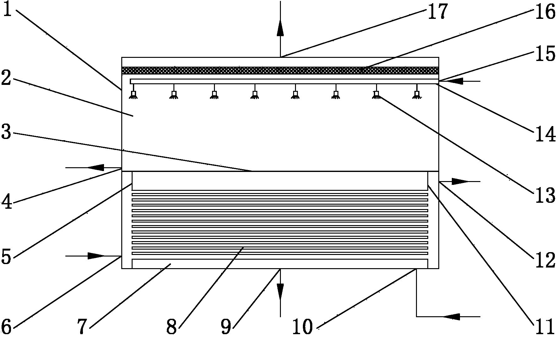
[0028] An evaporator for treating oily sewage, comprising an evaporator shell 1, the middle part of the evaporator shell 1 is fixedly connected with an intermediate partition 3, and the intermediate partition 3 can be welded, bonded, or connected by bolts and rubber pads , the evaporator shell 1 is divided into two completely independent airtight spaces, the evaporation chamber 2 and the condensation chamber 7, and there must be no leakage of liquid or gas between the evaporation chamber 2 and the condensation chamber 7; on the top wall of the evaporation chamber 2 or The upper part of the side wall is provided with a secondary steam outlet 17 and a hot feed liquid inlet 15; a concentrated water outl...


PUM


Abstract

The invention discloses an evaporator for treating oily sewage, which comprises an evaporator shell 1, wherein the evaporator shell 1 is divided into a evaporating chamber 2 and a condensing chamber 7 by a middle partition plate 3; the upper part of the top wall of side wall of the evaporating chamber 2 is provided with a secondary vapor outlet 17 and a hot liquor inlet 15, and the lower part is provided with a concentrated water outlet 4; and a first tube plate 5 and a second tube plate 11 are arranged in the condensing chamber 7, a heat exchange tube 8 is fixedly connected between the tube plates, the side wall of the condensing chamber 7 is provided with a liquor water inlet 6 and a liquor water outlet 12, and the bottom wall is provided with a condensing water outlet 9 and a heating vapor inlet 10. The invention avoids the problem that a fouling layer outside a tube of a horizontal tube evaporator is difficult to clean and the defects that a vertical tube falling film evaporator is high in installation accuracy requirement, high in initial investment and the like, and greatly lowers the initial investment and operation cost of oily sewage treatment equipment. Besides, the evaporator can be also used for the liquor concentrating and refining process in industries of chemical engineering, food, pharmacy and the like.

Description

technical field [0001] The invention belongs to the technical field of water treatment and relates to an evaporator for treating oily sewage. technical background [0002] A large amount of wastewater will be generated during the oil extraction process. According to statistics, for every 80 million barrels of crude oil produced in the world, 250 million barrels of oil extraction wastewater are produced. Calculated at a water-to-oil ratio of 3:1, the water content reaches 70%. The global oil extraction water content rate has increased over the past ten years and has continued to climb. With the improvement of oil extraction technology, the water content of crude oil is also increasing. The comprehensive water content of crude oil in most oilfields in my country has reached 80%, and some even reach 90%. The annual output of oil production wastewater is about 410 million tons, which has become the main Oily sewage sources. [0003] Oil extraction wastewater has the following c...

Claims


Application Information

Patent Timeline
IPC IPC(8): C02F1/04C02F1/40
Inventor 张铭任建波张晓晨齐春华谢春刚吕庆春
Owner TIANJIN SEA WATER DESALINATION & COMPLEX UTILIZATION INST STATE OCEANOGRAPHI
Learn More