Combined type composite material floor heating trough plate and manufacturing method thereof

A composite material and combined technology, which is applied in the field of building decoration materials, can solve the problems of difficult pipeline maintenance, difficult maintenance, and increased effective floor height occupation, etc., and achieves good floor heating conductivity, high thermal conductivity, and simple process. Effect

Active Publication Date: 2014-09-10
安徽圣源橡塑科技有限公司
View PDF12 Cites 7 Cited by
  • Summary
  • Abstract
  • Description
  • Claims
  • Application Information

AI Technical Summary

Problems solved by technology

[0002] The traditional floor heating installation and construction method is to first lay water / electric heating pipes, and then fix the concrete bean stone layer. The installation and construction are difficult, the construction period is long, and the maintenance after installation is difficult.
After the floor heating is installed, if the pipeline is damaged during use, it is difficult to repair the pipeline
The installation of floor heating requires the construction steps of pipe clips, cable ties and steel mesh, which is difficult to construct. At the same time, due to the cement curing period, the construction progress is about 1 week
And after the floor heating is installed, there is a problem that the pipe is heated and expanded, causing the pipe to break and the cement leveling layer to crack
In the traditional floor heating installation, due to the existence of cement bean stone layer, keel layer, and floor heating layer, the thickness of the entire floor heating layer is about 13 cm, which increases the occupation of the effective floor height

Method used


Image

  • Combined type composite material floor heating trough plate and manufacturing method thereof
  • Combined type composite material floor heating trough plate and manufacturing method thereof
  • Combined type composite material floor heating trough plate and manufacturing method thereof

Examples


Embodiment Construction

[0052] Attached below figure 1 The following examples are only used to illustrate the technical solutions of the present invention more clearly, but not to limit the protection scope of the present invention.

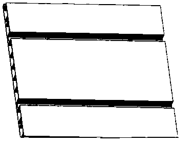
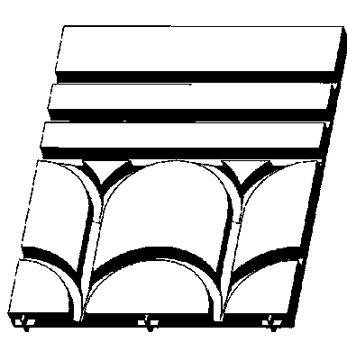
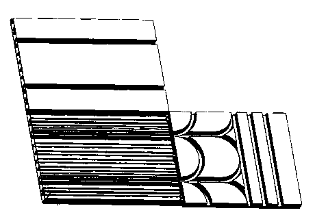
[0053] A combined composite material floor heating trough, which is composed of a straight tube composite material trough module and an elbow type composite material trough module; each composite trough has a double-layer structure, and the main layer is a functional polymer alloy plate. The upper layer is a functional aluminum foil heat conduction layer.

[0054] Among them, the main channel plate of the straight tube composite material channel plate module is completed by the extrusion process (see figure 1 ), the width is 336mm, the plate thickness is 28mm, and the length is arbitrary. The plate groove has two straight pipe grooves, the depth of the pipe groove is 18mm, the distance between the center line of the pipe groove is 168mm, and the distance from the cent...


PUM

PropertyMeasurementUnit
lengthaaaaaaaaaa
widthaaaaaaaaaa
thicknessaaaaaaaaaa

Abstract

The invention relates to the field of building decoration materials, in particular to a combined type composite material floor heating trough plate and a manufacturing method of the trough plate. The combined type composite material floor heating trough plate is composed of a straight pipe type composite material trough plate module and a bend type composite material trough plate module, and plate edges and plate heads are spliced through lock catch structures of tenons and mortises. The two modules can be freely combined according to the required number and the hot source requirements of a room structure, single-S structure or double-S structure arranging and mounting of a heating cable and a hot water pipe for floor heating are achieved, and even radiation of the heat source is ensured. The composite trough plate is of a double-layer structure, a body layer is made of functional polymer alloy sheet materials, and the body layer resists to heat, has the inflaming retarding effect and is high in strength. A functional aluminum foil heat conduction layer is arranged on the upper layer and is rapid in heat conduction and high in heat efficiency utilization rate.

Description

technical field [0001] The invention relates to the field of building decoration materials, in particular to a combined composite floor heating channel plate and a preparation method thereof. Background technique [0002] The traditional floor heating installation and construction method is to first lay water / electric heating pipes, and then fix the concrete bean stone layer. The installation and construction are difficult, the construction period is long, and the maintenance after installation is difficult. After floor heating is installed, if the pipeline is damaged during use, it is difficult to repair the pipeline. The installation of floor heating requires the construction steps of pipe clamps, cable ties and steel mesh, which is difficult to construct. At the same time, due to the cement curing period, the construction progress is about 1 week. And after the floor heating is installed, there is a problem that the pipe is heated and expanded, causing the pipe to break ...

Claims


Application Information

Patent Timeline
Patent Type & Authority Applications(China)
IPC IPC(8): E04F15/06C08L27/06C08L27/24C08L55/02C08L25/12C08L33/20C08L33/12C08L25/16C08K13/06C08K9/00C08K3/26
Inventor 王新志李明王磊张中巨
Owner 安徽圣源橡塑科技有限公司
Why Eureka
Try Eureka