Detection box used for detecting light transmittance of printing and dyeing wastewater

A technology for printing and dyeing wastewater and light transmittance, which is applied in the preparation of test samples, transmittance measurement, settling tanks, etc. It can solve problems such as nonlinearity, deviation between pH meter measured value and actual value, and extremely high control accuracy. Achieve the effect of low cost, good separation effect and small volume

Active Publication Date: 2014-09-10
林丽兵
View PDF7 Cites 50 Cited by
  • Summary
  • Abstract
  • Description
  • Claims
  • Application Information

AI Technical Summary

Problems solved by technology

[0004] In view of the above problems, the Chinese Patent No. CN203238083U discloses a printing and dyeing wastewater treatment equipment that automatically adjusts the amount of treatment chemicals. However, in the actual treatment process, since the pH meter is inserted into the printi

Method used


Image

  • Detection box used for detecting light transmittance of printing and dyeing wastewater
  • Detection box used for detecting light transmittance of printing and dyeing wastewater
  • Detection box used for detecting light transmittance of printing and dyeing wastewater

Examples


Embodiment 1

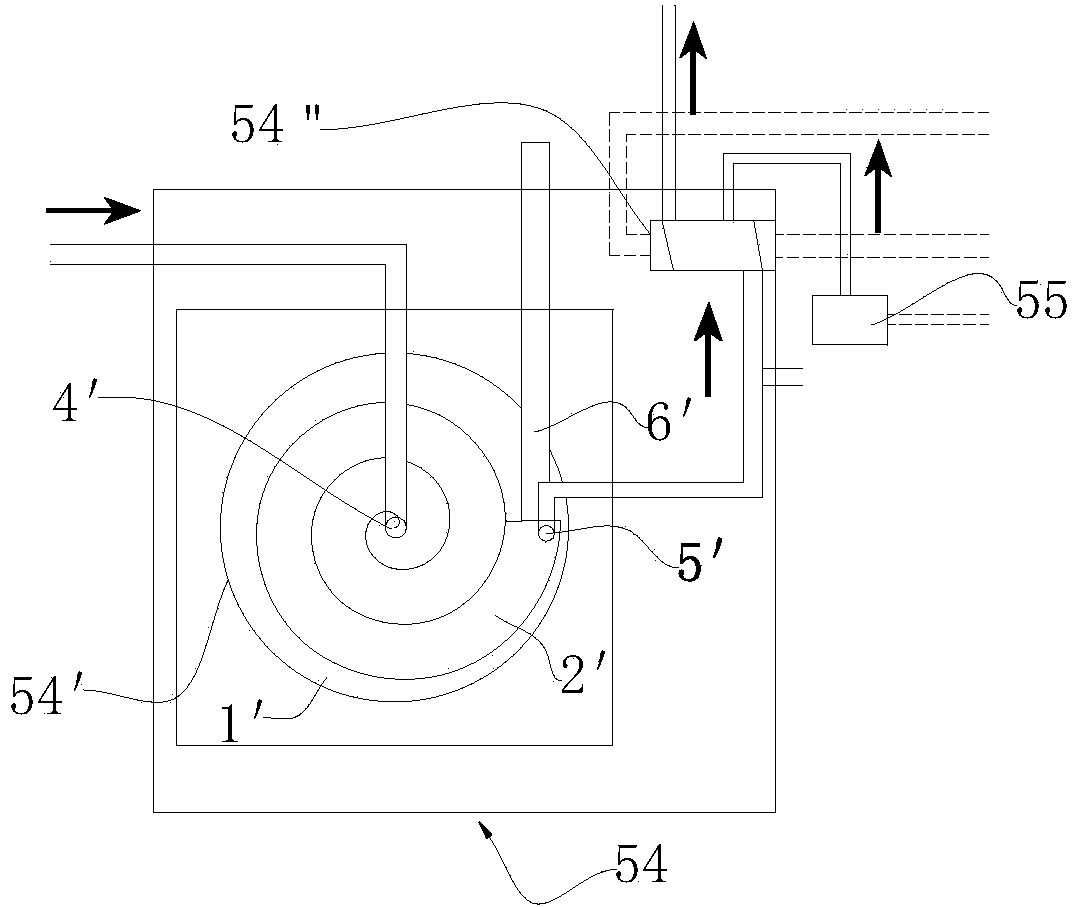
[0018] Such as figure 1 The detection box for detecting the light transmittance of printing and dyeing wastewater is shown, the detection box includes a box body, a settling device 54' connected in sequence to the sampling water inlet pipe 51, and a light detection device 54 for detecting the light transmittance of the printing and dyeing wastewater supernatant ", the sedimentation device 54' and the light detection device 54" are all in the box. The box body is provided with an input end for connecting the printing and dyeing wastewater sampling inlet pipe, a first output end for connecting the printing and dyeing wastewater sampling outlet pipe and a second output end for discharging sediment.

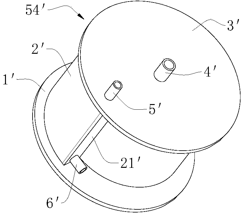
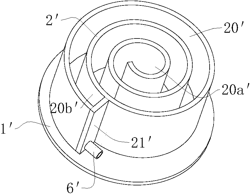
[0019] see figure 1 , figure 2 with image 3 As shown, the role of the settling device 54' is to quickly settle the solids in the sewage to separate the sewage supernatant, which is convenient for the optical detection device 54" used to detect the light transmittance of the prin...

Embodiment 2

[0023] The difference between this embodiment and embodiment 1 is that this embodiment adopts another kind of settling device, such as Figure 5 As shown, the settling device consists of a rectangular box 10' and a plurality of baffles 20' interlaced and fixed on the inner walls of the two sides of the rectangular box 10'. One end of the rectangular box 10' is provided with a water inlet pipe 40'. The rectangular box The bottom of the other end of the 10' is provided with a sedimentation outlet 60', and a supernatant outlet 50' is opened on the top wall near the other end of the rectangular box 10', and the supernatant outlet 50' is connected to the The printing and dyeing wastewater inlet pipe 1 ″ in the optical detection device 54 ″ for the light transmittance of the printing and dyeing wastewater supernatant. The rest are repeated in Example 1, and will not be described in detail.


PUM


Abstract

The invention relates to detection equipment used in a printing and dyeing wastewater physicochemical treatment system, in particular to a detection box used for detecting the light transmittance of printing and dyeing wastewater. The detection box comprises a box body, a sedimentation device and a light detecting device used for detecting the light transmittance of clear liquid on the printing and dyeing wastewater. The box body is provided with an input end used for being connected with a printing and dyeing wastewater sampling water inlet tube, a first output end used for being connected with a printing and dyeing wastewater sampling water outlet tube and a second output end used for discharging sediments. The sedimentation device and the light detecting device are all placed in the box body. The detection box can be used for conducting light transmittance capacity detection on the printing and dyeing water entering the inside of the detection box, measured light intensity signals are measured to be used as usable control signals, so that the clarity of the separated clear liquid is expressed, and human eyes are replaced to observe whether the printing and dyeing wastewater is fully flocculated or not.

Description

technical field [0001] The invention belongs to the field of sewage treatment, in particular to a detection device used in a physical and chemical treatment system of printing and dyeing wastewater. Background technique [0002] China is the world's largest producer and exporter of textiles and clothing, so the printing and dyeing industry is closely related to it, and the wastewater discharge of the printing and dyeing industry is one of the key industries that cause water pollution in my country. Compared with other industries, printing and dyeing wastewater has a large amount of wastewater discharge , deep color, high content of refractory organic matter, unstable water quality and so on. [0003] For the treatment of printing and dyeing wastewater, the existing treatment technologies mainly treat printing and dyeing wastewater through physical and chemical treatment and biochemical treatment in order, so as to degrade harmful substances and meet the discharge standards. ...

Claims


Application Information

Patent Timeline
IPC IPC(8): G01N21/59G01N1/34B01D21/02
CPCB01D21/02G01N1/34G01N21/59
Inventor 宣尧杭
Owner 林丽兵
Why Eureka
Try Eureka