High-power plasma gas purification device

A gas purification device and plasma technology, which is applied in gas treatment, separation methods, and separation of dispersed particles, can solve problems such as weak discharge current, high breakdown voltage, and human discomfort, so as to increase the effective discharge area and improve discharge efficiency. Power, the effect of improving purification efficiency

Active Publication Date: 2022-01-04
HUAZHONG UNIV OF SCI & TECH
View PDF10 Cites 0 Cited by
  • Summary
  • Abstract
  • Description
  • Claims
  • Application Information

AI Technical Summary

Problems solved by technology

[0004] For air purification, the breakdown voltage of air is high, and the existing DBD low-temperature plasma generators are difficult to take into account both the ventilation rate and the discharge intensity. The DBD discharge in the form of a packed bed can fully purify the gas to be treated. However, the large wind resistance leads to low processing efficiency and cannot operate in a large area of ​​work; the existing long-gap discharge gas purification device, by changing the electrode structure such as needle electrode discharge, wire electrode discharge, etc., generates a local distorted electric field to generate discharge. However, the local extremely uneven electrode structure leads to strong distortion of the electric field in a small area, so that the electric field strength drops rapidly at a certain distance from the electrode, and the discharge usually generated is in the corona discharge mode, the discharge current is weak, and the discharge itself The dissipated power is low, the active ingredients produced, such as active nitrogen oxides, high-energy electrons, and the content of ultraviolet radiation are small, and the sterilization effect is poor
And because the discharge channel is not completely turned on, the discharge is concentrated near the electrode, and the contact area between the gas to be treated and the plasma is small, making the treatment efficiency low
At the same time, the proportion of ozone produced by corona discharge is too high, which can easily cause discomfort to the human body and cause corrosion to objects.
In addition, the existing structure increases the electric field intensity by adding ground electrodes to enhance the discharge, such as the existing needle-plate discharge. The needle electrode array structure is used to improve the processing efficiency, and when the gas to be processed passes through, it will still pass through a certain proportion of the non-discharge area, which cannot be completely purified

Method used


Image

  • High-power plasma gas purification device
  • High-power plasma gas purification device
  • High-power plasma gas purification device

Examples


Embodiment 1

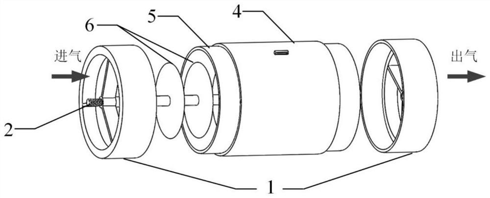
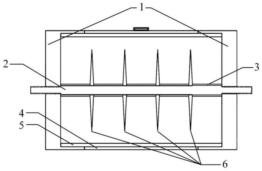
[0036] like figure 1 , figure 2 As shown, the high power plasma gas purification apparatus, including: insulating fastening member 1, metal shaft 2, metal ground casing 4, insulating dieter 5, and metal electrode 6, the metal electrode is a metal wafer electrode .

[0037] A metal wafer electrode is provided, the metal wafer electrode is provided, and the metal wafer electrode is attached to the metal shaft 2 by the perforation kit in which the center of the center is turned on by the metal shaft 2. .

[0038] The insulative dielectric cartridge 5 is located between the metal wafer electrode and the metal ground casing, forming a DBD discharge structure, avoiding discharge conversion into an arc or spark form, and reduces the voltage amplitude applied to the high voltage electrode, resulting in only a partial region discharge. The insulating dielectric cartridge is preferably a high temperature resistant to high temperature resistance. According to the available voltage amplitude,...

Embodiment 2

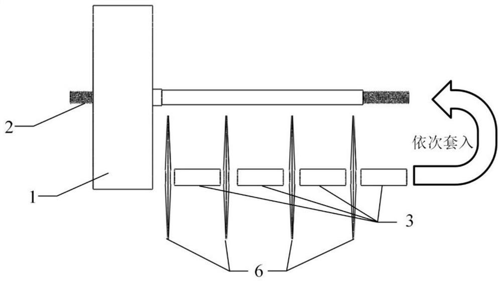
[0046] like image 3 As shown, in fact, in the present embodiment, in the present embodiment, the metal wafer electrode and the metal shaft 2 are not integrated, but the detachable structure. Each individual metal wafer electrode is spaced apart by the metal sleeve 3 and conducts, the metal wafer electrode and the metal sleeve are sequentially set on the metal shaft 2. By changing the length of the metal sleeve 3, the number of the serial metal wafer electrodes can be changed. When the environmental dust content is more, consider the cleaning of the device to maintain the discharge efficiency, this detachable structure of the electrode.

Embodiment 3

[0048] Unlike Example 1, in the present embodiment, the metal wafer electrode is placed with a metal shaft. By changing the position of the center hole of the insulating fastening member, the distance from the inner wall of the metal wafer electrode and the insulating medium can be adjusted, that is, the discharge gap between the electrode and the insulating dielectric bar, such as Figure 4 Indicated. In the case of limited power output capability, the eccentric placing facilitates control discharge in the same discharge cycle. Since the area electric field in the gap is higher, it will be discharged, so that the discharge is not limited to a moment, and can reduce discharge The resulting peak current reduces the parameter requirements of the power supply; the area of ​​the gap, due to the low electric field, after discharging, the discharge current can be eliminated, and the average power in the entire discharge cycle can not be reduced The active ingredient produced by the disch...


PUM

PropertyMeasurementUnit
Edge thicknessaaaaaaaaaa
Thicknessaaaaaaaaaa
Edge thicknessaaaaaaaaaa

Abstract

The invention discloses a high-power plasma gas purification device, and belongs to the technical field of gas purification. The gas purification device comprises a metal shaft and a metal electrode arranged on the metal shaft in a sleeving mode; a circumferential linear discharge face is formed on the edge of the metal electrode, an insulating medium cylinder is arranged outside the metal electrode, and a metal grounding shell is further arranged outside the insulating medium cylinder; and the metal electrode is connected with a high-voltage electrode of a high-voltage power supply through the metal shaft, and a grounding port is led out of the metal grounding shell and connected with a grounding end of the high-voltage power supply. According to the gas purification device, the discharge power can be improved on the basis of increasing the discharge area, more plasma active components are generated, and the purification efficiency of to-be-treated gas is improved.

Description

Technical field [0001] The present invention belongs to the field of gas purification technology, and more particularly to a high power plasma gas purification device. Background technique [0002] With the improvement of living standards, air quality problems are more and more attention. Low temperature plasma is used as a kind of emerging technology, often studied in biomedical fields such as sterilization, wound treatment in the past two decades, which contains a large number of active nitrogen oxides, ultraviolet radiation, and high energy electrons to kill bacterial viruses. Have a good effect. Compared to the traditional ultraviolet lamp, disinfectous water and other air murderous methods, low temperature plasma gas purification technology has the advantages of safe, efficient side effects, low cost, etc. . [0003] Among them, the low temperature plasma generated by the DIElectric Barrier Discharge (DBD), due to the blocking of the medium, can avoid discharge of the arc or...

Claims


Application Information

Patent Timeline
IPC IPC(8): B01D53/32
CPCB01D53/323B01D2259/818
Inventor 聂兰兰刘凤梧吕洋卢新培
Owner HUAZHONG UNIV OF SCI & TECH
Why Eureka
Try Eureka