A high-power plasma gas purification device

A gas purification device, plasma technology, applied in gas treatment, separation method, dispersed particle separation, etc., can solve the problems of weak discharge current, high breakdown voltage, and failure to operate, so as to increase the effective discharge area and reduce the breakdown Breakthrough voltage, effect of increasing unevenness

Active Publication Date: 2022-08-02
HUAZHONG UNIV OF SCI & TECH
View PDF0 Cites 0 Cited by
  • Summary
  • Abstract
  • Description
  • Claims
  • Application Information

AI Technical Summary

Problems solved by technology

[0004] For air purification, the breakdown voltage of air is high, and the existing DBD low-temperature plasma generators are difficult to take into account both the ventilation rate and the discharge intensity. The DBD discharge in the form of a packed bed can fully purify the gas to be treated. However, the large wind resistance leads to low processing efficiency and cannot operate in a large area of ​​work; the existing long-gap discharge gas purification device, by changing the electrode structure such as needle electrode discharge, wire electrode discharge, etc., generates a local distorted electric field to generate discharge. However, the local extremely uneven electrode structure leads to strong distortion of the electric field in a small area, so that the electric field strength drops rapidly at a certain distance from the electrode, and the discharge usually generated is in the corona discharge mode, the discharge current is weak, and the discharge itself The dissipated power is low, the active ingredients produced, such as active nitrogen oxides, high-energy electrons, and the content of ultraviolet radiation are small, and the sterilization effect is poor
And because the discharge channel is not completely turned on, the discharge is concentrated near the electrode, and the contact area between the gas to be treated and the plasma is small, making the treatment efficiency low
At the same time, the proportion of ozone produced by corona discharge is too high, which can easily cause discomfort to the human body and cause corrosion to objects.
In addition, the existing structure increases the electric field intensity by adding ground electrodes to enhance the discharge, such as the existing needle-plate discharge. The needle electrode array structure is used to improve the processing efficiency, and when the gas to be processed passes through, it will still pass through a certain proportion of the non-discharge area, which cannot be completely purified

Method used


Image

  • A high-power plasma gas purification device
  • A high-power plasma gas purification device
  • A high-power plasma gas purification device

Examples


Embodiment 1

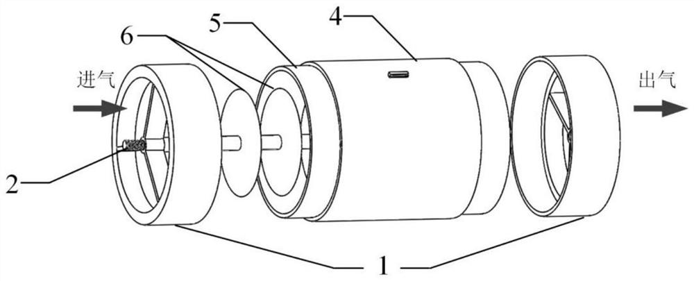
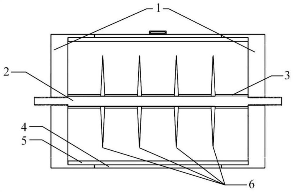
[0036] like figure 1 , figure 2 As shown, the high-power plasma gas purification device in this embodiment includes: an insulating fastening part 1, a metal shaft 2, a metal grounding casing 4, an insulating medium cylinder 5 and a metal electrode 6, and the metal electrode is a metal disc electrode .

[0037] A piece of metal disc electrode is arranged on the metal shaft 2 at a certain distance. The metal disc electrode is sleeved on the metal shaft 2 through the hole in the center, and is connected to the high-voltage pulse power supply or the high-voltage electrode of the AC power supply through the metal shaft 2. .

[0038] The insulating medium cylinder 5 is located between the metal disc electrode and the metal grounding shell, forming a DBD discharge structure, avoiding the discharge from being converted into discharge in the form of arc or spark, reducing the voltage amplitude applied to the high-voltage electrode, resulting in only partial area discharge. The insu...

Embodiment 2

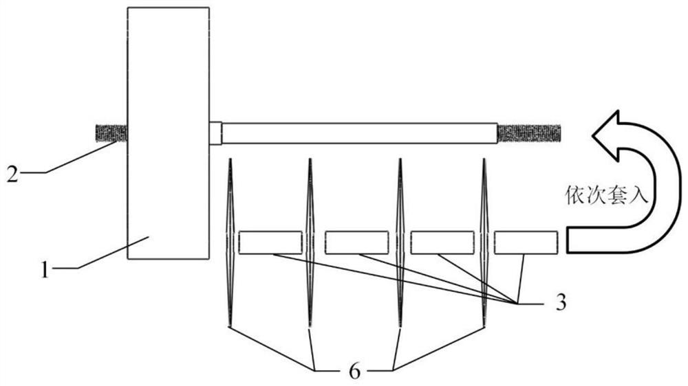
[0046] like image 3 As shown, the difference from Embodiment 1 is that in this embodiment, the metal disc electrode and the metal shaft 2 are not integrally designed, but are detachable structures. Each independent metal disc electrode is separated by a metal sleeve 3 and conducts, and the metal disc electrode and the metal sleeve are sleeved on the metal shaft 2 in sequence. By changing the length of the metal sleeve 3 , the number of metal disc electrodes connected in series can be changed. When the dust content in the environment is high, considering the cleaning of the device to maintain the efficiency of the discharge action, such a detachable structure of the electrode is preferred.

Embodiment 3

[0048] Different from Embodiment 1, in this embodiment, the metal disc electrode and the metal shaft are eccentrically placed. By changing the position of the central hole of the insulating fastening part, the distance between the metal disc electrode and the inner wall of the insulating medium cylinder can be adjusted, that is, the discharge gap between the electrode and the insulating medium cylinder can be changed, such as Figure 4 shown. In the case of limited power output capacity, eccentric placement is beneficial to control the sequence of discharges in the same discharge cycle. Since the electric field in the area with a short gap is higher, the discharge will be discharged first, so that the discharge is not limited to a certain moment, and the discharge can be reduced. The generated peak current reduces the parameter requirements for the power supply; in the area with a long gap, due to the low electric field, it will be discharged after, which can prolong the durat...


PUM

PropertyMeasurementUnit
thicknessaaaaaaaaaa
thicknessaaaaaaaaaa
poweraaaaaaaaaa

Abstract

The invention discloses a high-power plasma gas purification device, which belongs to the technical field of gas purification. The gas purification device comprises: a metal shaft and a metal electrode sleeved on the metal shaft, the edge of the metal electrode forms a circumferential linear discharge surface, an insulating medium cylinder is arranged outside the metal electrode, and the insulating medium cylinder is also A metal grounding shell is provided; the metal electrode is connected to the high-voltage pole of the high-voltage power supply through the metal shaft, and a grounding port is drawn out of the metal grounding shell to connect to the grounding end of the high-voltage power supply. The gas purification device of the present invention can increase the discharge power on the basis of increasing the discharge area, generate more plasma active components, and improve the purification efficiency of the gas to be treated.

Description

technical field [0001] The invention belongs to the technical field of gas purification, and more particularly, relates to a high-power plasma gas purification device. Background technique [0002] With the improvement of living standards, air quality problems have attracted more and more people's attention. As an emerging technology, low-temperature plasma has been used in biomedical fields such as sterilization and wound treatment in the past two decades. It contains a large amount of reactive nitrogen oxides, ultraviolet radiation, and high-energy electrons to kill bacteria and viruses There are good results. Compared with traditional air disinfection methods such as ultraviolet lamps and disinfection water, low-temperature plasma gas purification technology has the advantages of safety, high efficiency, small side effects, and low cost. Therefore, in recent years, low-temperature plasma gas purification has become a major research hotspot. . [0003] Among them, the l...

Claims


Application Information

Patent Timeline
Patent Type & Authority Patents(China)
IPC IPC(8): B01D53/32
CPCB01D53/323B01D2259/818
Inventor 聂兰兰刘凤梧吕洋卢新培
Owner HUAZHONG UNIV OF SCI & TECH
Why Eureka
Try Eureka