
Self-adapting charging method for vehicle-mounted power battery

A charging method and power battery technology, which are applied in the direction of charging/discharging of secondary batteries, battery circuit devices, and repair/maintenance of secondary batteries, etc. And other issues

Active Publication Date: 2014-09-10
SOUTHEAST UNIV
View PDF4 Cites 39 Cited by
  • Summary
  • Abstract
  • Description
  • Claims
  • Application Information

AI Technical Summary

Problems solved by technology

This charging method can reduce the damage to the battery, but it cannot eliminate the polarization phenomenon during battery charging, especially in the constant voltage stage, the occurrence of polarization phenomenon greatly reduces the charging efficiency of the battery and prolongs the charging time of the battery
There are also some domestic literatures that use intelligent charging to charge the battery, that is, the charging power source automatically determines the charging parameters according to the charging state of the battery, so that the charging current is kept near the maximum acceptable charging curve from the beginning to the end, but most of the literature is only in the research stage. In the simulation stage, the actual implementation requires higher charging power, which will greatly increase the cost of the entire charging management system
[0004] On the other hand, although the use of high current can greatly reduce the charging time of the battery, the high current will also cause the battery temperature to rise continuously during charging. If it cannot be effectively controlled, it will not only shorten the service life of the battery, but may even cause a fire

Method used


Image

  • Self-adapting charging method for vehicle-mounted power battery
  • Self-adapting charging method for vehicle-mounted power battery
  • Self-adapting charging method for vehicle-mounted power battery

Examples


Embodiment Construction

[0052] Hereinafter, detailed reference will be given to the embodiments of the present invention in conjunction with the accompanying drawings.

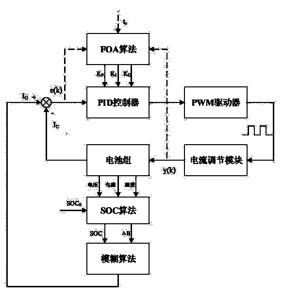
[0053] Reference figure 1 , Figure 4 with Figure 5 , An adaptive charging control system for vehicle power batteries includes a main controller module 307, a battery sensor module 304, a temperature acquisition module 303, a protection equalization module 302, a memory module 308, a current adjustment module 311, a display module 309, and at least one set of batteries 301.

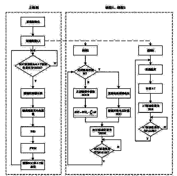
[0054] The software flowchart of the adaptive charging method for the vehicle power battery of this embodiment is as image 3 As shown, after determining the battery type and PID parameters, in order to achieve the purpose of dynamically adjusting the charging current and keeping the charging current near the maximum acceptable charging curve from beginning to end, the control algorithm is described as follows:

[0055] The main controller receives the battery charge...


PUM


Abstract

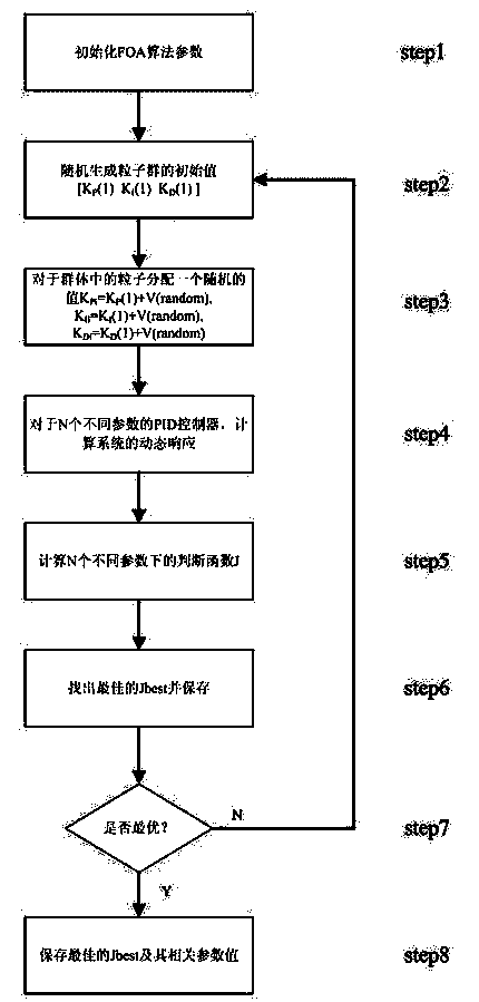
The invention discloses a self-adapting charging method for a vehicle-mounted power battery. The method comprises the steps that when the battery is charged, a main control module calculates the state of charge (SOC) of the battery according to battery current, voltage and temperature information collected by a battery sensor module; a temperature variable quantity delta H and the SOC are input to a fuzzy controller in the main controller module, and the optimal charging current in the current state is output through a fuzzy control algorithm; A PID controller controls a PWM driver to produce a control signal with a proper duty ratio; a current regulation module dynamically regulates charging current according to the control signal, and therefore the purpose of self-adapting charging is achieved. In order to make the charging current quickly and accurately reach the optimum value, a fruit fly optimization algorithm (FOA) is adopted to dynamically regulate parameters of the PID controller. According to the self-adapting charging method, the charging current can be regulated in a self-adapting mode, the charging time of the battery can be effectively shortened, the charging efficiency of the battery can be effectively enhanced, and the service life of the battery can be effectively prolonged.

Description

【Technical Field】 [0001] The invention relates to an adaptive charging method, in particular to an adaptive charging method using nickel hydrogen and lithium batteries as vehicle power batteries. 【Background technique】 [0002] With people's attention to environmental protection and energy conservation, electric vehicles and hybrid vehicles have attracted more and more attention. As the power source of both, power batteries need to ensure that they provide stable and reliable output during driving. At the same time, fast, balanced and safe charging of the power battery can prolong the service life of the battery and improve the efficiency and performance of the battery. [0003] The current charging method for power batteries generally uses constant current-constant voltage charging, that is, charging the battery with a constant current in the initial stage of charging, and when the battery voltage reaches the constant voltage threshold, it will switch to the constant voltage charg...

Claims


Application Information

Patent Timeline
IPC IPC(8): H02J7/00H01M10/44
CPCY02E60/10
Inventor 秦文虎许庆黄林孙觉非
Owner SOUTHEAST UNIV
Learn More