III-type compensation control system of Cuk-type switch converter

A switching converter, compensation network technology, applied in the field of microelectronics, can solve problems such as circuit instability, achieve the effect of simple control loop and enhanced load regulation rate

Inactive Publication Date: 2014-09-10
SOUTHEAST UNIV
View PDF2 Cites 5 Cited by
  • Summary
  • Abstract
  • Description
  • Claims
  • Application Information

AI Technical Summary

Problems solved by technology

However, unlike the power stage of the Buck-type switching power converter, there are two inductors and capacitors in the power stage of the Cuk-type circuit structure, resulting in two pairs of conjugate poles and a pair of conjugate zeros (such as Figure 4 ), if the Type III compensation network of the traditional voltage mode BUCK switching converter (such as figure 1 ) is directly used in Cuk-type switching converters, which will make the circuit unstable

Method used


Image

  • III-type compensation control system of Cuk-type switch converter
  • III-type compensation control system of Cuk-type switch converter
  • III-type compensation control system of Cuk-type switch converter

Examples


Embodiment Construction

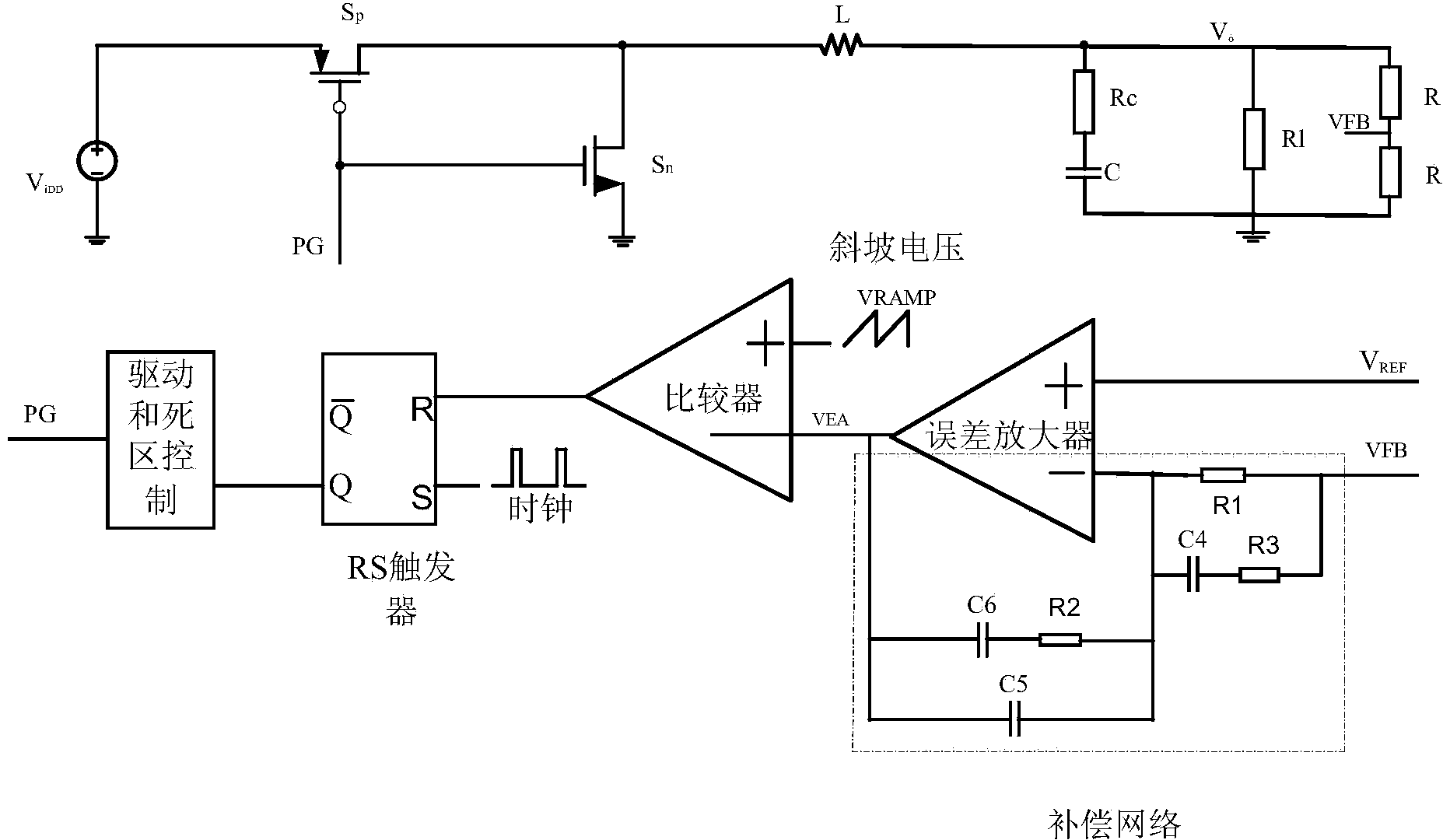
[0021] Such as figure 1 , BUCK type circuit and control system includes power stage and control stage. The power stage is composed of an inductor L, a capacitor C, the parasitic resistance Rc of the capacitor C, and power tubes Sp and Sn. One end of the inductor L is connected to the drain of Sp and the drain of Sn, the source of Sn is grounded, and the source of Sp is connected to The positive end of the power supply voltage VDD is connected, the other end of the inductor L is used as the output voltage Vo to connect the parasitic resistance Rc, the other end of Rc is connected to the capacitor C, the other end of the capacitor C is connected to the ground, and the resistor Rl is connected between the Vo terminal and the ground as Load Resistance.

[0022] The control stage includes a type III compensation network, a comparator, an RS flip-flop, a drive and dead-zone control circuit, and a feedback circuit composed of two identical resistors R in series. Type III compensation ...


PUM


Abstract

Disclosed is an III-type compensation control system of a Cuk-type switch converter. The Cuk-type switch converter comprises a primary power level circuit and a secondary power level circuit, and a control level comprises a closed system formed by a feedback circuit, a comparator, an RS (reset-set) trigger, a driving circuit and an III-type compensation network of a BUCK-type switch converter. The III-type compensation control system of the Cuk-type switch converter is characterized in the III-type compensation network of the BUCK-type switch converter is improved for controlling the Cuk-type switch convert, output of the improved III-type compensation network is compared with a ramp voltage access comparator, and on and off of a power tube of the Cuk-type switch converter is controlled by a duty ratio generated by a comparative result.

Description

Technical field [0001] The invention relates to a DC-DC switching power supply converter, in particular to a control method of a III-type compensation Cuk (Cuk) switching converter, which belongs to the field of microelectronics technology. Background technique: [0002] Organic Light Emitting Diode (OLED) has the characteristics of softness and transparency, clear picture quality, energy saving and environmental protection, and is regarded as the most promising next-generation flat display technology. The OLED display panel needs a positive power supply voltage and a negative power supply voltage to power it, so the design of negative voltage chips has become the mainstream trend in this field. Cuk type circuit has the advantages of low output voltage and current ripple and high efficiency. At the same time, Cuk circuit also has very good anti-noise ability and anti-interference ability. Therefore, Cuk-type circuits will gradually become a research focus. However, unlike the p...

Claims


Application Information

Patent Timeline
Patent Type & Authority Applications(China)
IPC IPC(8): H02M3/157
Inventor 孙伟锋肖哲飞张力文钱钦松刘斯扬陆生礼时龙兴
Owner SOUTHEAST UNIV
Why Eureka
Try Eureka