
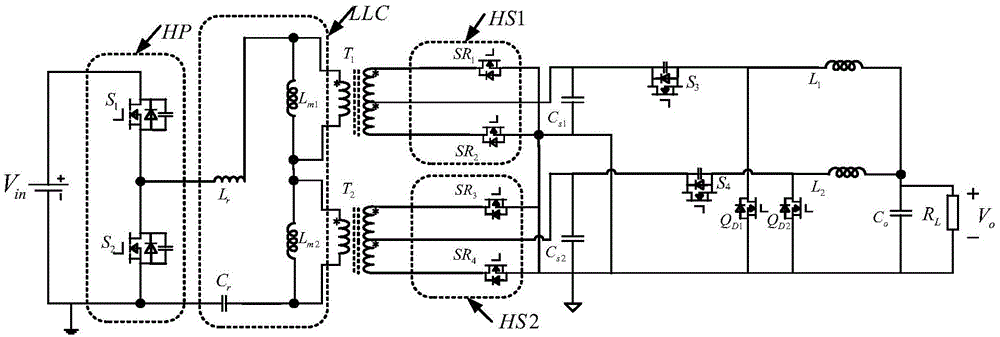
Transformer primary side series connection LLC and output parallel connection BUCK two-stage converter

A transformer secondary side, transformer technology, applied in the direction of output power conversion device, DC power input conversion to DC power output, instruments, etc., can solve the problem of reducing module output load characteristics, complex control system design, and the current sharing bus is susceptible to interference and other issues, to achieve reliable and efficient synchronous rectification, simplify the control link, and reduce the effect of EMI radiation

Active Publication Date: 2014-09-10
ZHEJIANG UNIV
View PDF4 Cites 37 Cited by
  • Summary
  • Abstract
  • Description
  • Claims
  • Application Information

AI Technical Summary

Problems solved by technology

The droop method realizes the current sharing of the parallel modules by changing the output internal resistance of the parallel modules, thus reducing the output load characteristics of the modules; while the active current sharing method requires a dedicated current sharing control circuit, which needs to detect the input or output current of each module. And the current sharing bus is susceptible to interference, so the design of the control system is complicated, the reliability is reduced, and the system cost is high

Method used


Image

  • Transformer primary side series connection LLC and output parallel connection BUCK two-stage converter
  • Transformer primary side series connection LLC and output parallel connection BUCK two-stage converter
  • Transformer primary side series connection LLC and output parallel connection BUCK two-stage converter

Examples


Embodiment approach

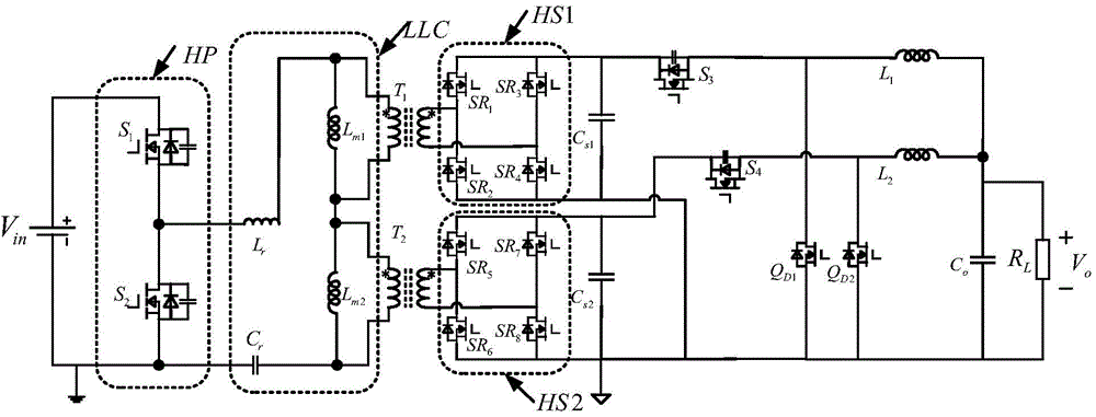
[0024] Such as figure 2 As shown, as the second embodiment of the present invention, the main circuit is composed of a front-stage fixed-frequency half-bridge LLC resonant converter and a rear-stage output terminal interleaved parallel BUCK circuit, wherein the front-stage fixed-frequency half-bridge LLC resonant converter consists of one Half-bridge bridge circuit HP, a resonance network LLC, two high-frequency isolation transformers T1, T2, two rectifier circuits HS1, HS2, and two bus capacitors Cs1 and Cs2. The half-bridge circuit HP is composed of switching tubes S1 and S2. The resonance network LLC is composed of a series resonance inductance Lr, the excitation inductances Lm1 and Lm2 of two high-frequency transformers, and a series resonance capacitor Cr. HS1 is composed of synchronous rectifier tubes SR1 and It is composed of SR2, SR3, and SR4, and HS2 is composed of synchronous rectifier tubes SR5, SR6, SR7, and SR8. Among them, the drain of the switch S1 is connected ...


PUM


Abstract

The invention discloses a transformer primary side series connection LLC and output parallel connection BUCK two-stage converter which comprises two high-frequency isolation transformers, wherein primary sides of the two high-frequency isolation transformers are connected in series and then connected into an LLC resonant network; the other end of the LLC resonant network is connected into a bridge circuit; secondary sides of the two high-frequency isolation transformers are sequentially connected with rectifying circuits and BUCK circuits; and output ends of the two BUCK circuits are staggered and connected in parallel. The converter can achieve zero voltage switch-on of switching tubes on the primary sides of the high-frequency transformers, and zero current switch-off of rectifying tubes on the secondary sides of the high-frequency transformers, so that the efficiency and the power density of the LLC converter are improved; and equal primary side voltage of two primary side series connection high-frequency transformers of a preceding-stage converter can be achieved based on control of the same duty ratio of the two BUCK circuits which are staggered and connected in parallel, so that the two high-frequency transformers share equallyinput power, magnetism equilibrium distribution of the high-frequency transformers is achieved, the reliability of the converter is improved, and the cost is lowered.

Description

Technical field [0001] The present invention belongs to the technical field of power electronics, and relates to the related technology of wide input high voltage, output low / high current, high frequency, high power density module power supply, in particular to a transformer primary side series LLC plus output parallel BUCK (buck chopper) Circuit) Two-stage converter. Background technique [0002] With the continuous development of science and technology, higher requirements are put forward for the efficiency, power density and reliability of DC / DC converters. The soft switching of the switching tube can realize zero loss during the switching process of the switching tube, and at the same time effectively suppress the voltage spike in the switching process of the switching tube and reduce the EMI radiation of the circuit, which improves the efficiency and reliability of the converter. The series voltage equalization of the primary side of the high-frequency transformer can effec...

Claims


Application Information

Patent Timeline
IPC IPC(8): H02M3/335H02M1/44
Inventor 石健将章江铭
Owner ZHEJIANG UNIV
Learn More