Deformed array antenna scattering performance analyzing method based on electromechanical coupling

An array antenna and analysis method technology, applied in the direction of electrical components, transmission monitoring, transmission system, etc., can solve the problems of deviation from the ideal design position, unpredictable, difficult phase difference, etc., to shorten the development cycle, reduce development costs, avoid The effect of antenna instability problems

Active Publication Date: 2014-09-10
XIDIAN UNIV
View PDF4 Cites 30 Cited by
  • Summary
  • Abstract
  • Description
  • Claims
  • Application Information

AI Technical Summary

Problems solved by technology

In general, it is very difficult to analytically determine the scattered field of the structure mode term, the scattered field of the antenna mode term, and the phase difference between the two
Moreover, the scattering field of the array antenna is the result of the joint contribution of the scattering field of all antenna elements in the array. At the same time, due to the limitation of the accuracy of machining equipment and assembly accuracy, as well as the influence of environmental loads such as vibration and thermal power consumption, the position of the array antenna elements will vary. Deviation from the ideal design position will lead to changes in the scattering field of the array antenna. Therefore, the impact of the offset of the array antenna unit position on the scattering performance urgently needs calculation methods and evaluation methods
[0004] At present, domestic and foreign scholars usually use numerical calculation methods when calculating the scattering performance of array antennas, such as Tanaka T, Nishioka Y, Inasawa Y, et al. MoM analysis of radiation and scattering of broadband array antenna. Proceedings of 2013URSI International Symposium on Electromagnetic Theory, 2013 The method of moments is used to calculate the radiation and scattering performance of the tapered slot array antenna. Although this method can calculate the RCS of the array antenna, the calculation process is complicated, and the calculation of the scattered field of the large-scale array antenna requires longer calculation time. and more storage space
For this reason, many approximate calculation methods have emerged for the calculation of array antenna scattering field, such as in Lu B, Gong S X, et al. Optimum spatial arrangement of array elements for suppression of grating-lobes of radar cross section. IEEE Antennas and Wireless Propagation Letters ,VOL.9,2010, on the basis of not considering the mutual coupling and edge effects, the simplified RCS expression of the array antenna scattering field is derived, and then the array antenna scattering pattern function trend is used to predict the array antenna scattering The change trend of the total RCS of the field. Although this method can conveniently and quickly estimate the change trend of the total RCS of the array antenna scattering field, it cannot predict and calculate the influence of the antenna unit offset on the array antenna scattering field by this method.
Scholars at home and abroad have also done a lot of research on the influence of antenna unit position offset on the electrical performance of array antennas, such as Wang Cong-si, Duan Bao-yan, Zhang Fu-shun, et al.Analysis of performance of active phased array antenna with distorted plane error. International Journal of Electronics, VOL.96, NO.5, 2009, based on the phase error analysis between antenna elements, established a radiation field electromechanical coupling model, which can only be used to calculate the effect of antenna element offset on radiation The influence of the field performance, the influence of the position offset of the antenna unit on the scattering performance cannot be calculated

Method used


Image

  • Deformed array antenna scattering performance analyzing method based on electromechanical coupling
  • Deformed array antenna scattering performance analyzing method based on electromechanical coupling
  • Deformed array antenna scattering performance analyzing method based on electromechanical coupling

Examples


Embodiment Construction

[0054] The present invention will be further described below in conjunction with the accompanying drawings and embodiments.

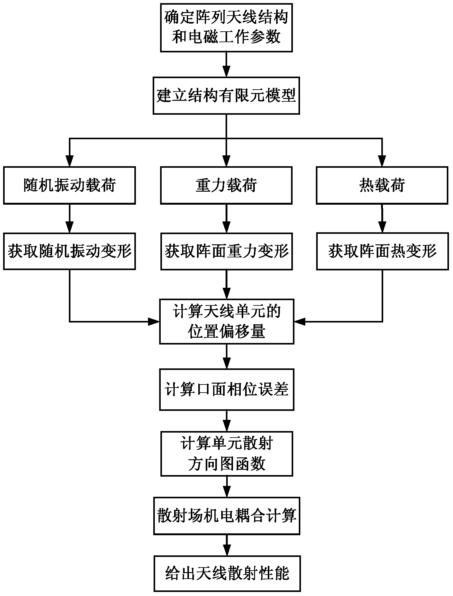
[0055] refer to figure 1 As shown, a method for analyzing the scattering performance of the deformed array antenna based on electromechanical coupling of the present invention, the specific steps are as follows:

[0056] Step 1, determine the geometric model parameters, material properties and electromagnetic working parameters of the array antenna.

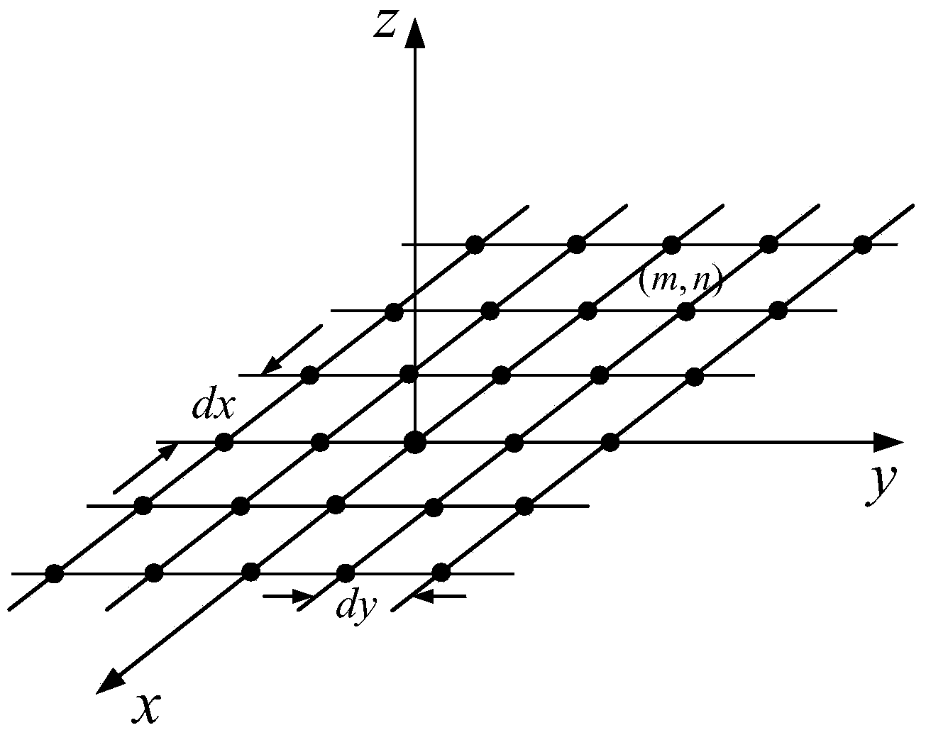
[0057] 1.1. The finite element model of the array antenna structure is determined by the shape, size, and antenna element type of the array antenna, and the structural parameters of the array antenna are obtained, including the antenna aperture, that is, the length L in the array (x, y direction) x and width L y , the number of rows M of antenna elements in the x, y direction, the number of columns N and the spacing d of the antenna elements in the x, y direction x , d x ,Such as figure 2 shown;

[...


PUM


Abstract

The invention discloses a deformed array antenna scattering performance analyzing method based on electromechanical coupling. The deformed array antenna scattering performance analyzing method based on the electromechanical coupling includes that determining geometrical model parameters, material attributes and electromagnetic working parameters of an array antenna; building a finite element model of the antenna; determining constraint conditions and random vibration load, gravity load and thermal load environments of the finite element model, calculating the array surface deformation of the array antenna under the constraint conditions and load environments, and extracting the position offsets of antenna center nodes of the finite element model of the antenna under the conditions; accumulating to obtain the total position offset of the antenna; calculating the spatial phase difference of two adjacent antenna unit scatting fields in the array surface to obtain an aperture phase difference; calculating an antenna unit scattering pattern; calculating an array antenna scattering field pattern; analyzing the influence of the array structure deformation on the antenna scattering performance under the load environments. The deformed array antenna scattering performance analyzing method based on the electromechanical coupling is used for quantitatively evaluating the influence of the array surface structure deformation on the antenna scattering performance under the load environments and guiding the array antenna structure design, cooling design and scattering performance simulation analysis and evaluation.

Description

technical field [0001] The invention belongs to the technical field of antennas, and in particular relates to a method for predicting the scattering performance of an array antenna. The invention can be used to evaluate the influence of the antenna unit position offset caused by the deformation of the array under the load environment on the scattering performance of the array antenna, and guide the structural design, heat dissipation design and simulation analysis and evaluation of the scattering performance of the array antenna. Background technique [0002] Antennas are widely used in radio systems such as communications, broadcasting, television, radar, and navigation. They play the role of spreading radio waves and are an essential device for effectively radiating and receiving radio waves. Array antennas can form radiation characteristics different from general unit antennas, especially can form radiation that is much stronger than unit antennas pointing to a certain pa...

Claims


Application Information

Patent Timeline
Patent Type & Authority Applications(China)
IPC IPC(8): H04B17/00
Inventor 王从思王伟锋余涛康明魁保宏孟娟陈光达米建伟王猛
Owner XIDIAN UNIV
Why Eureka
Try Eureka