
A Method Of And A Device And An Electronic Controller For Mitigating Stick-slip Oscillations In Borehole Equipment

A technology of electronic controller and drilling equipment, which is applied in the direction of mechanical vibration control, drilling automatic control system, drilling equipment, etc., can solve the problems of sinusoidal waveform approximation and the inability to correctly describe the physical behavior of drilling equipment, etc. Stick-slip, the effect of reducing stick-slip oscillation

Active Publication Date: 2014-09-10
ENGIE电气工程有限公司
View PDF7 Cites 3 Cited by
  • Summary
  • Abstract
  • Description
  • Claims
  • Application Information

AI Technical Summary

Problems solved by technology

[0014] The problem with this known method is that the frequency approximation does not correctly describe the physical behavior of the drilling equipment in the viscous mode where the bottom hole assembly comes to a complete standstill, since the velocity of the bottom hole assembly is clearly equal to zero
Additionally, the fact that the bottom-hole assembly rotates at a relatively low speed makes it more difficult to obtain a sufficiently accurate approximation of the sinusoidal waveform, and because practical drilling systems exhibit non-linear behavior

Method used


Image

  • A Method Of And A Device And An Electronic Controller For Mitigating Stick-slip Oscillations In Borehole Equipment
  • A Method Of And A Device And An Electronic Controller For Mitigating Stick-slip Oscillations In Borehole Equipment
  • A Method Of And A Device And An Electronic Controller For Mitigating Stick-slip Oscillations In Borehole Equipment

Examples


Embodiment Construction

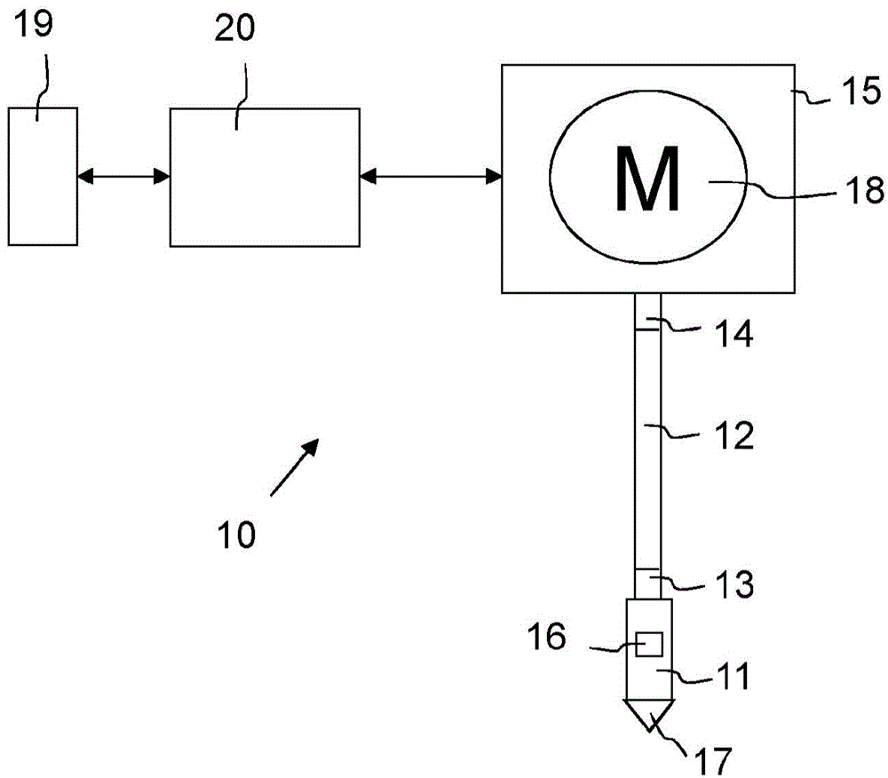
[0081] figure 1A typical drilling rig 10 of a drilling rig for drilling boreholes in earth formations is shown in a schematic manner. The cutting tool used to drill these boreholes is called a drill bit 17 and is connected to the bottom hole assembly BHA11 at the bottom end face 13 of the drill wire 12 . At the top end face 14 of the drilling line, the drilling line 12 is coupled to a rotary drive system 15 .

[0082] Borehole string 12 comprises a length of hollow tubular or borehole pipe threaded together end-to-end. Typical borehole cables are several kilometers long, eg 0-10 km, and borehole pipes may have an outer diameter of about 100-300 mm and a wall thickness of about 10-50 mm. The BHA11 comprises a heavier pipe, which may have an outer diameter of about 250-500 mm and a wall thickness of about 100 mm, for example called a drill collar. The length of the BHA is typically in the range of 100-300m. The drilling string 12 is very slender compared to its length.

[0...


PUM


Abstract

A method for mitigating stick-slip oscillations in borehole equipment while drilling a borehole in an earth formation is described. The borehole equipment is modelled by a computational model for computer simulation. The model has elements representing a particular mechanical and physical behavior of the borehole equipment. In a simulated stick mode of the borehole equipment, physical quantities are loaded to the elements, which quantities represent an initial state of the borehole equipment prior to a transition from stick mode to slip mode. From a simulation of such transition, a time response of rotational speeds of a drive system and bottom hole assembly of the borehole equipment is recorded and a lower limit of the rotational speed of the drive system is determined for which the rotational driven speed of the bottom hole assembly is zero.

Description

technical field [0001] The present invention generally relates to drilling equipment for drilling boreholes in formations of the earth. More specifically, the present invention relates to a method, device and electronic controller for mitigating stick-slip oscillations in such a drilling rig while drilling and a drilling device equipped with and according to such a method, device and electronic controller. Background technique [0002] The term borehole generally refers to the result of a drilling operation into the earth vertically, horizontally and / or deflected using a drill string comprising a drill bit at its lower end. ). At the upper or top end of the drilling line, the drilling line is driven at the surface by a drive system, called a top drive or rotary table. The top drive or wheel is driven by an electric motor or any other type of drive motor to provide rotary motion to the drill bit in the borehole. [0003] Typically, a borehole string is an elongated structu...

Claims


Application Information

Patent Timeline
IPC IPC(8): E21B44/00
CPCE21B44/00G05D19/02E21B41/0092G05B13/04
Inventor 安德烈·威尔特曼
Owner ENGIE电气工程有限公司
Learn More