
Double movable-coil servo type ultra-low frequency rotational vibrating table

A servo-type, ultra-low-frequency technology, which is applied in the direction of vibrating fluid, can solve the problems of expensive vibration table, high minimum measurement frequency, high calibration cost, etc., and achieve the effect of simple structure, low manufacturing difficulty and good low-frequency performance

Inactive Publication Date: 2014-09-17
INST OF ENG MECHANICS CHINA EARTHQUAKE ADMINISTRATION +2
View PDF3 Cites 3 Cited by
  • Summary
  • Abstract
  • Description
  • Claims
  • Application Information

AI Technical Summary

Problems solved by technology

[0002] At present, there are angular vibration vibration tables driven by torque motors at home and abroad. The measurement principle is generally calibrated by laser interferometry once. The frequency range is 5-500Hz, but the vibration table is expensive and the minimum measurement frequency is high.
In addition, the bearing capacity of the angular vibrating table is generally less than 10kg, while the mass of the rotational signal measuring instrument for measuring low-frequency or ultra-low-frequency components of the earthquake is much greater than 10kg. Low cost, high calibration costs, etc., so there is an urgent need for a cheap, ultra-low-frequency rotary vibration table to calibrate the sensitivity, frequency response and other parameters of seismic rotary measuring instruments

Method used


Image

  • Double movable-coil servo type ultra-low frequency rotational vibrating table
  • Double movable-coil servo type ultra-low frequency rotational vibrating table
  • Double movable-coil servo type ultra-low frequency rotational vibrating table

Examples


Embodiment Construction

[0015] Embodiments of the present invention will be further described in detail below in conjunction with the accompanying drawings.

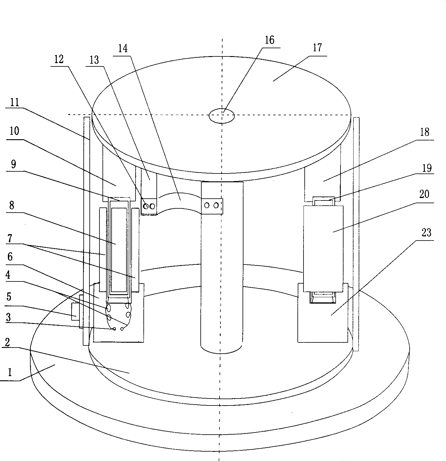
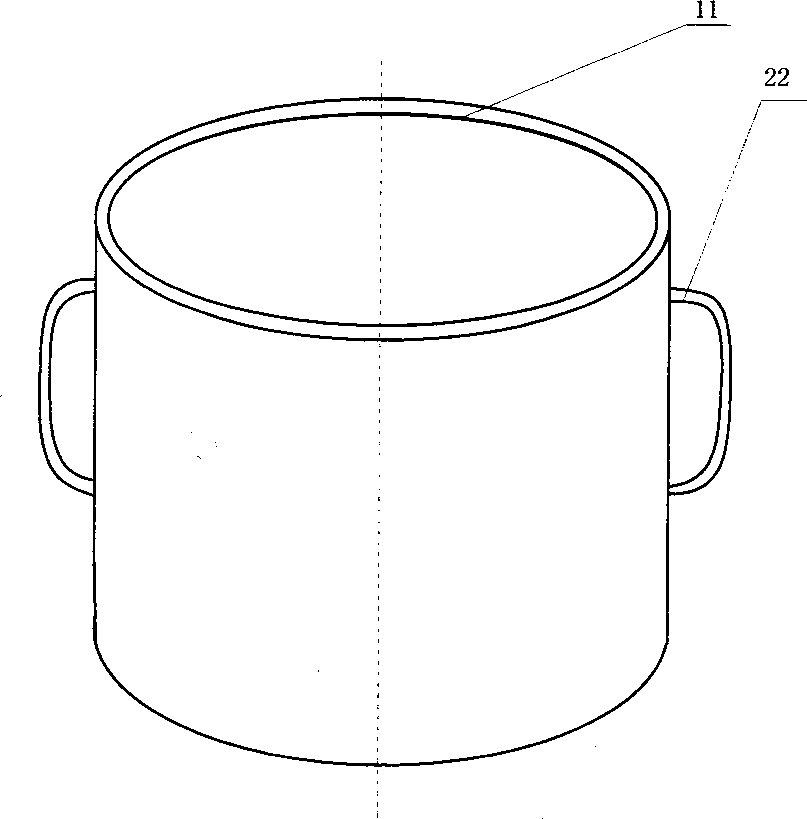
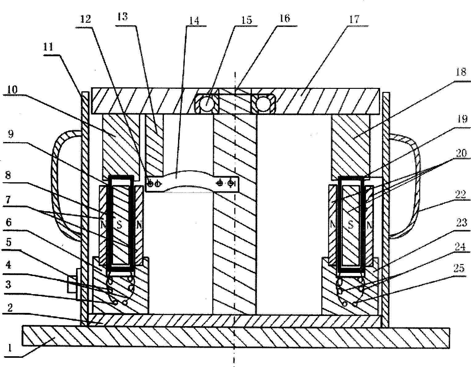
[0016] Depend on Figure 1-Figure 6 It can be seen that the present invention includes a base plate 2 and a housing 11. The base plate 2 is provided with a turntable, a drive system and a feedback system. The turntable includes a vertical shaft 16, and the lower end of the vertical shaft 16 is installed on the base plate 2. The upper end of the vertical shaft 16 passes through the The precision bearing 15 is connected to the circular rotating table top 17, and the shaft section of the vertical shaft 16 located below the precision bearing 15 is fixedly connected to one end of the spring leaf 14, and the other end of the spring leaf 14 is connected to the circular rotating table top 17 through a spring connector 13. The drive system includes a signal source 26, a drive coil 19, and a magnetic circuit 20. The upper end of the drive coil 19 is inst...


PUM


Abstract

The invention relates to a double movable-coil servo type ultra-low frequency rotational vibrating table which comprises a bottom plate and a housing, wherein a turning table, a driving system and a feedback system are arranged on the bottom plate, the turning table comprises an upright shaft, the upright shaft is positioned at a shaft segment below a precise bearing and is fixedly connected with one end of a spring leaf, the other end of the spring leaf is connected with a circular rotary table board through a spring connector, the driving system comprises a signal source, a drive coil and a magnetic circuit, the feedback system comprises a feedback amplifier, a reaction coil and a magnetic circuit, the reaction coil and the drive coil are symmetrically mounted about the upright shaft, the magnetic circuit of the feedback system and the magnetic circuit of the driving system are symmetrically mounted about the upright shaft, the magnetic circuit comprises a permanent magnet and a concave magnetic yoke, and the two side arms of the magnetic yoke and a gap between two side surfaces of the permanent magnet form a magnetic gap. The double movable-coil servo type ultra-low frequency rotational vibrating table provided by the invention has a simple structure, is reasonable in design, high in calibration accuracy, low in calibration cost, small in low frequency lower limit and can achieve calibration on all rotational signal measuring devices.

Description

technical field [0001] The invention relates to a rotary vibrating table, in particular to a double moving coil servo type ultra-low frequency rotary vibrating table. Background technique [0002] At present, there are angular vibration vibration tables driven by torque motors at home and abroad. The measurement principle is generally calibrated by laser interferometry once. The frequency range is 5-500Hz, but the vibration table is expensive and the minimum measurement frequency is high. In addition, the bearing capacity of the angular vibrating table is generally less than 10kg, while the mass of the rotational signal measuring instrument for measuring low-frequency or ultra-low-frequency components of the earthquake is much greater than 10kg. Therefore, there is an urgent need for a low-cost, ultra-low-frequency rotary vibration table to calibrate parameters such as sensitivity and frequency response of seismic rotary measuring instruments. Contents of the invention ...

Claims


Application Information

Patent Timeline
Patent Type & Authority Applications(China)
IPC IPC(8): B06B1/04
Inventor 杨学山高峰匙庆磊刘华泰车晓军董玲杨立志杨巧玉王南
Owner INST OF ENG MECHANICS CHINA EARTHQUAKE ADMINISTRATION
Learn More