
substrate support

A substrate support and bearing technology, which is applied to electrical components, electrical solid devices, semiconductor devices, etc., can solve the problems of easily damaged rollers or bearings, large unilateral force, and too small rollers, so as to reduce fractures. risk, effect of increasing intensity

Active Publication Date: 2017-04-12
EVERDISPLAY OPTRONICS (SHANGHAI) CO LTD
View PDF3 Cites 0 Cited by
  • Summary
  • Abstract
  • Description
  • Claims
  • Application Information

AI Technical Summary

Problems solved by technology

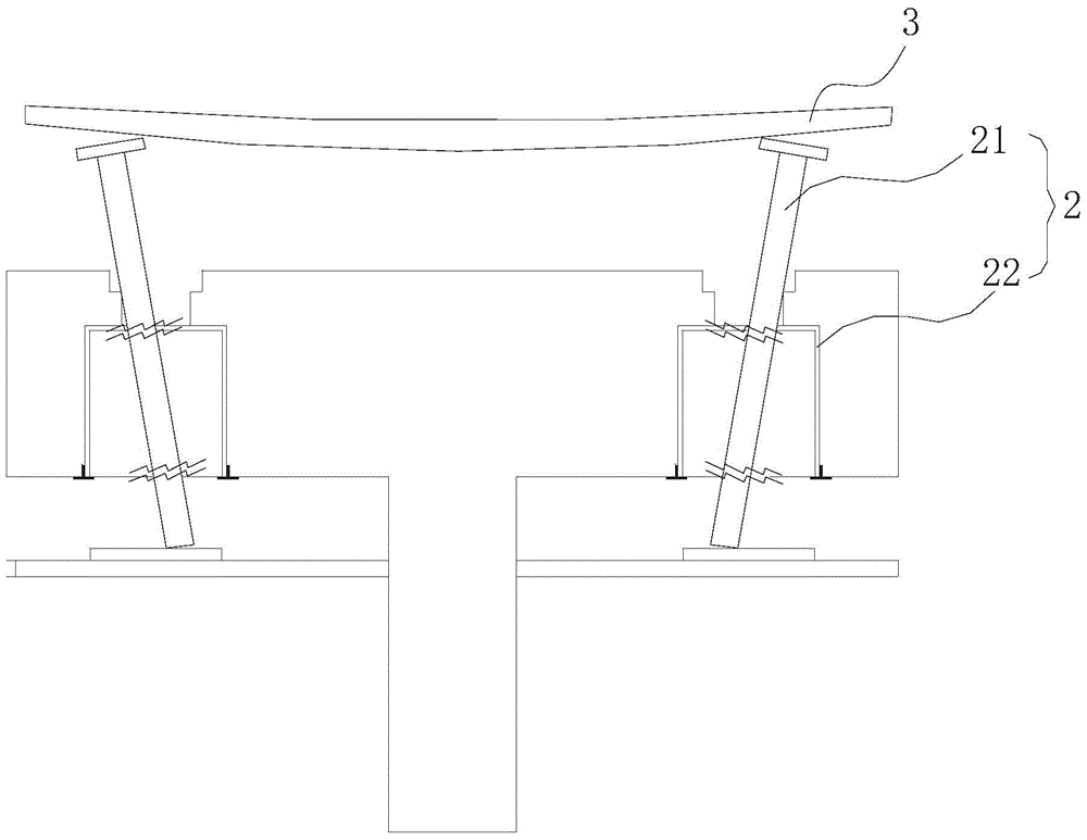
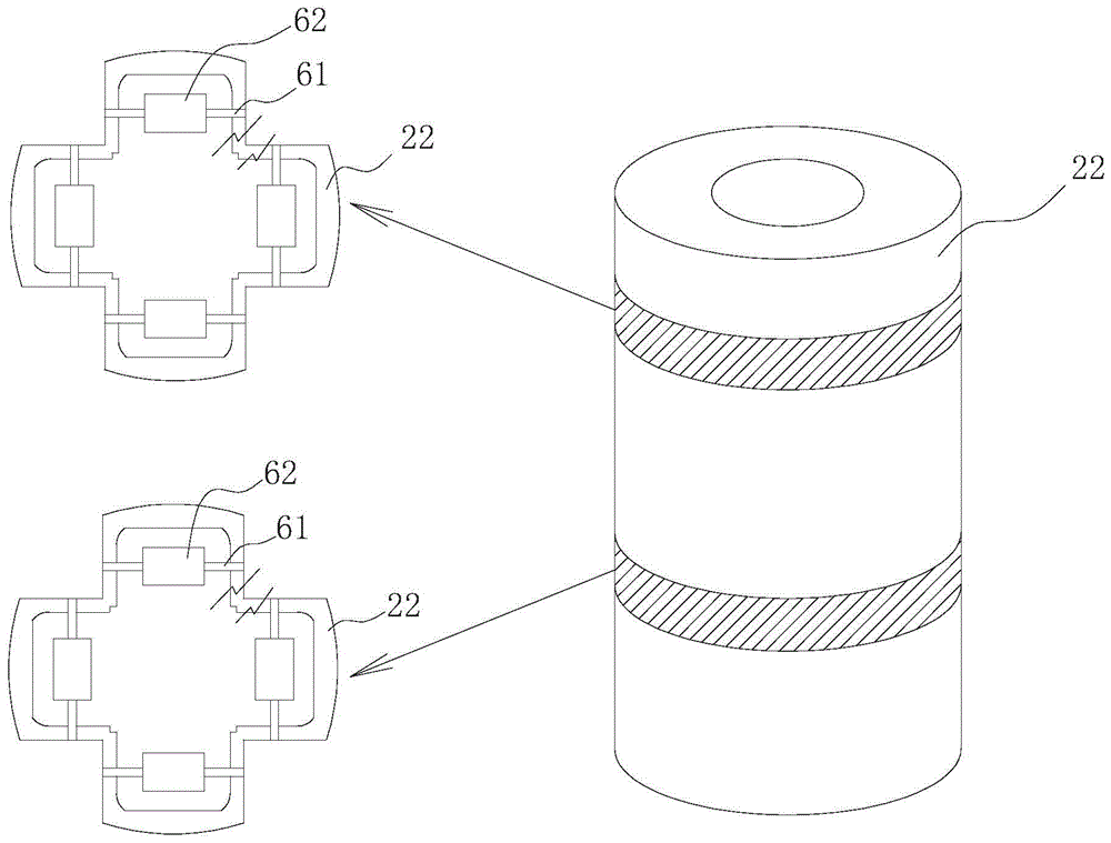
In the existing structure of the substrate support 2, when the glass is lifted by the lifting pin 21, the entire lifting pin 21 is in an inclined state due to the bending of the glass plate 3 (such as figure 1 shown), the roller 62 in the bushing 22 (as figure 2 Shown) Excessive force on one side
Therefore, the bushing structure in this receiving device will cause the following disadvantages: (1) The inner gap of the bushing is too small, as long as a certain degree of particulate matter is accumulated, the lifting pin will be stuck in the bushing, causing fragments or breaking of the lifting pin ; (2) The volume of the drum is too small, resulting in too small contact area between the lifting pin and the drum. When the lifting pin is tilted, the force point of the drum falls at the right angle between the vertical bearings, which will make it easier to damage the drum or the bearing. It may cause the lifting pin to be stuck and cause fragments, or cause the lifting pin to bend excessively, eventually causing internal damage or even breaking the lifting pin

Method used


Image

  • substrate support
  • substrate support
  • substrate support

Examples


Embodiment Construction

[0046] The technical content of the present invention is further described below in conjunction with accompanying drawing and embodiment:

[0047] The receiving device provided by the embodiments of the present invention may be applicable to any testing room, processing room, or system that needs to support a substrate. For example, in a thin film field effect transistor (TFT) deposition process for manufacturing OLEDs, such a receiving device for supporting a substrate is needed in a deposition chamber.

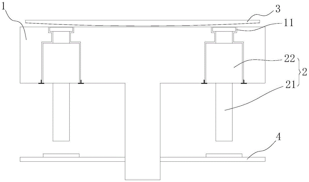
[0048] image 3 A structural schematic diagram of a longitudinal section of a receiving device for supporting a substrate according to a first embodiment of the present invention is shown. Specifically, the receiving device includes a machine platform 1 and a plurality of substrate supports 2 . Among them, in image 3 In the longitudinal section of the receiving device shown, a substrate supporting member 2 is provided on both sides of the center line of the machine 1 . ...


PUM


Abstract

The invention discloses a substrate supporting piece which comprises a bush, a lifting pin and at least one bearing mechanism. The bush is provided with a longitudinal through hole penetrating through the two ends of the bush. At least part of the lifting pin is arranged in the through hole, and can move in the through hole in the longitudinal direction. The bearing mechanisms are arranged in the through hole and located on the periphery of the lifting pin to support the lifting pin in a rolling mode. Each bearing mechanism comprises two parallel first bearing pieces and two parallel second bearing pieces, the first bearing pieces are perpendicular to the second bearing pieces, the first bearing pieces and the second bearing pieces are arranged in a staggered mode in the longitudinal direction of the bush, and the lifting pin or the bearing pieces can be prevented from being broken abnormally.

Description

technical field [0001] The invention relates to the field of substrate support, and in particular to a substrate support and a receiving device for supporting a substrate. Background technique [0002] Nowadays, in the manufacturing process of many electronic devices such as OLEDs, operations such as etching, vapor deposition, deposition, coating, etc. need to be performed on a substrate (such as a glass substrate). The equipment for realizing these operations must have a receiving device for supporting the glass substrate. In existing receiving devices for supporting glass substrates, key components (such as support pins and bearings) in the receiving device are often damaged due to the bending of the glass substrate by gravity, which further affects the quality of the above operations. [0003] figure 1 A structural schematic view of a longitudinal section of an existing receiving device for supporting a glass substrate is shown. figure 2 It is a structural schematic d...

Claims


Application Information

Patent Timeline
Patent Type & Authority Patents(China)
IPC IPC(8): H01L21/683H01L51/56
CPCH01L21/68742
Inventor 黄德伦许修齐
Owner EVERDISPLAY OPTRONICS (SHANGHAI) CO LTD
Learn More