
Atmospheric visibility detection device based on cavity ring-down technology and application method

A technology of atmospheric visibility and detection devices, which is applied in the field of optical fiber sensing and visibility measurement, can solve the problems of dust pollution in optical windows, fluctuations in light source power, expensive prices, etc., and achieve the effects of improved detection sensitivity, stable performance, and increased absorption optical path

Inactive Publication Date: 2014-09-24
XI'AN INST OF OPTICS & FINE MECHANICS - CHINESE ACAD OF SCI +1
View PDF3 Cites 9 Cited by
  • Summary
  • Abstract
  • Description
  • Claims
  • Application Information

AI Technical Summary

Problems solved by technology

Its advantage is that it can measure visibility data in a large range, but its disadvantage is that it is expensive, and it is a huge waste if it is only used for visibility measurement
At the same time, there are also problems such as light source power fluctuations and dust pollution on optical windows.

Method used


Image

  • Atmospheric visibility detection device based on cavity ring-down technology and application method
  • Atmospheric visibility detection device based on cavity ring-down technology and application method
  • Atmospheric visibility detection device based on cavity ring-down technology and application method

Examples


Embodiment 1

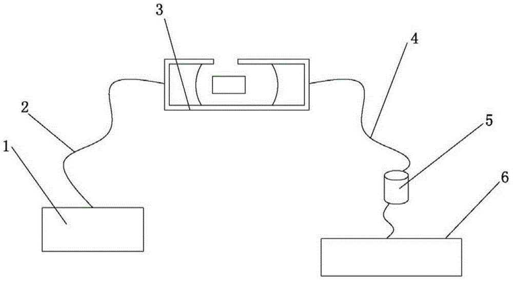
[0081] Such as Figure 5 As shown, the device includes a light source 1 arranged in sequence, an introduction optical fiber 2, a first coupler 9, a special optical fiber 10, a second coupler 11, a photodetector 5 and a data processing unit 6; during operation: the light emitted by the light source 1 The pulse enters an optical fiber arm of the first coupler 9 with a high splitting ratio through the leading optical fiber 2, and then enters the special optical fiber 10 closely. The main function of the special optical fiber 10 is to contact the light wave with the sample to be tested in the external environment, so that the energy of the light wave is absorbed by the sample. The special optical fiber 10 can be an existing photonic crystal optical fiber or a D-type optical fiber. Most of the light wave after passing through the special optical fiber 10 enters one fiber arm of the second coupler 11 and is output to the first coupler 9 by the fiber arm, and a small part of the rem...

Embodiment 2

[0084] Such as Image 6 As shown, the device includes a light source 1, an acousto-optic modulator 12, an input optical fiber 2, an input collimator 7, an optical resonant cavity 3, an output collimator 8, an output optical fiber 4, a photodetector 5 and The data processing unit 6 is used to calculate the light loss data to obtain the visibility value of the detected sample.

[0085] The specific working principle is:

[0086] Firstly, a continuous laser light is injected into an optical resonant cavity through a light source (the optical resonant cavity includes a cavity shell, a first reflector installed in the cavity shell, a second reflector and a piezoelectric ceramic scanner), and then the The piezoelectric ceramic (PZT) of the two mirrors scans the length of the cavity so that a certain longitudinal mode of the cavity matches the longitudinal mode of the laser. When the energy in the cavity reaches a certain threshold, the acousto-optic modulator is quickly turned off ...


PUM


Abstract

The invention belongs to the technical field of optical fiber sensing and visibility measurement, and particularly relates to an atmospheric visibility detection device based on the cavity ring-down technology and an application method. The device comprises a light source, a lead-in optical fiber, a resonant cavity, a lead-out optical fiber, a photoelectric detector and a data processing unit for calculating the optical loss data to obtain the visibility value of the detected sample arranged in sequence. The data processing unit obtains the loss of optical wave in the resonant cavity according to the characteristics of the resonant cavity and finally determines the visibility value of the detected sample through the optical loss. The device provided by the invention is compact in structure, the method is simple and easy to understand and convenient to implement, the detection accuracy of the detected sample visibility and the detection performance stability are greatly improved, and the device and method are applicable to the fields such as highway traffic, navigation, aviation and atmospheric pollutant monitoring.

Description

technical field [0001] The invention belongs to the technical field of optical fiber sensing and visibility measurement, in particular to an atmospheric visibility detection device and application method based on cavity ring-down technology. Background technique [0002] Visibility is an important atmospheric optical characteristic parameter, and also an important meteorological parameter that affects people's daily life and travel. In the fields of highway traffic, aviation, navigation, air pollutant monitoring and other fields, there is a demand for visibility measurement. There are many definitions of visibility, among which the more scientific definition is the so-called meteorological visible range. Meteorological visible range is defined as the distance traveled when the parallel light emitted by an incandescent lamp with a color temperature of 2700 Kelvin propagates in the atmosphere and its power attenuates to 5% of the initial value. [0003] At present, the visib...

Claims


Application Information

Patent Timeline
IPC IPC(8): G01N21/17
Inventor 阮驰王允韬冯丽丽陶圣
Owner XI'AN INST OF OPTICS & FINE MECHANICS - CHINESE ACAD OF SCI
Learn More