Eureka AIR delivers breakthrough ideas for toughest innovation challenges, trusted by R&D personnel around the world.

Reluctance Motor

A reluctance motor, inductance technology, applied in electric components, synchronous generators, synchronous motors for single-phase current, etc., can solve the problem of difficult to obtain large torque, can not expect high-efficiency drive (efficiency, etc., to achieve high-efficiency Self-excitation function, the effect of avoiding the reduction of the reluctance torque and preventing the self-excitation from being blocked

Active Publication Date: 2014-09-24
SUZUKI MOTOR CORP
View PDF8 Cites 10 Cited by
  • Summary
  • Abstract
  • Description
  • Claims
  • Application Information

AI Technical Summary

Problems solved by technology

Each type of reluctance motor has the following problems compared with a reluctance torque driven type motor (motor) using a permanent magnet embedded in the rotor side: When the reluctance motor is a reluctance torque type reluctance motor only When, it is difficult to obtain high torque
However, excitation energy needs to be input from the outside, so high-efficiency driving cannot be expected (inefficiency is inevitable)

Method used


Image

  • Reluctance Motor
  • Reluctance Motor
  • Reluctance Motor

Examples


Embodiment Construction

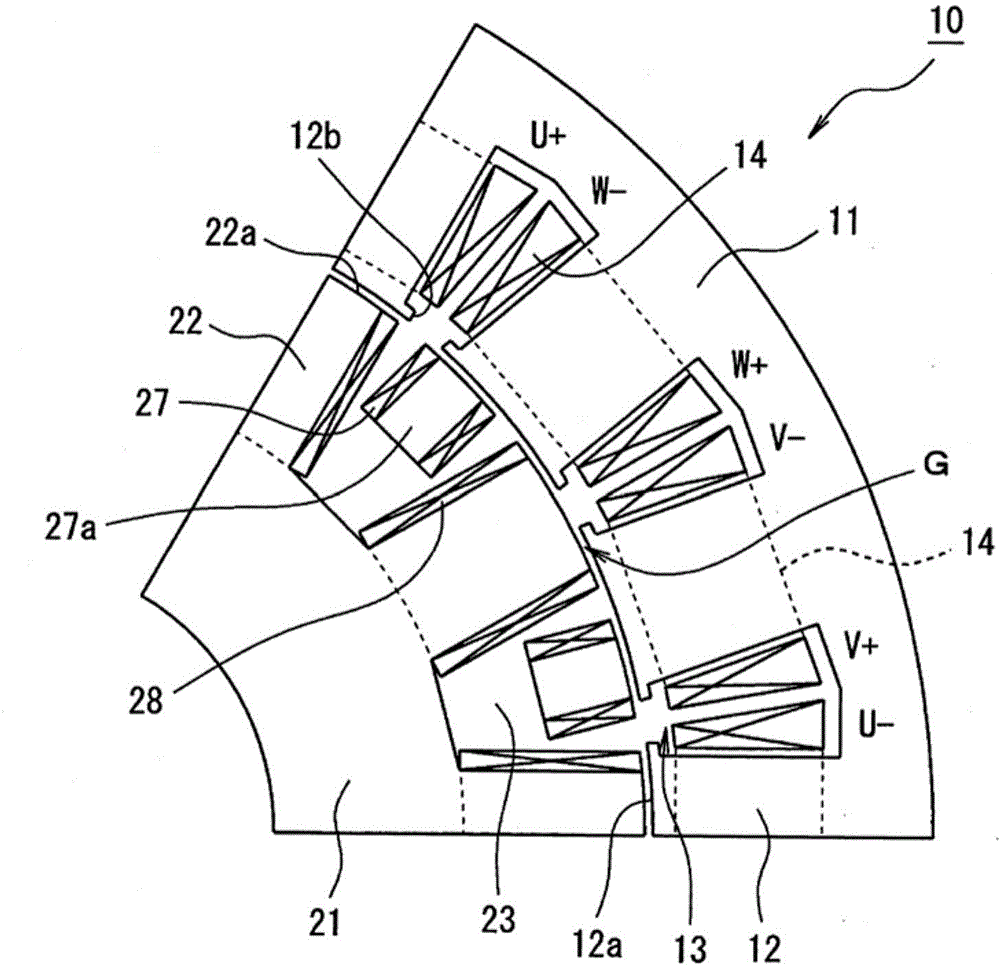
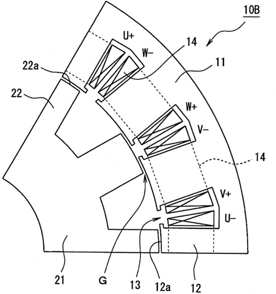
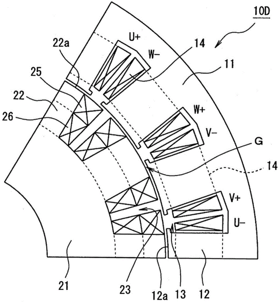
[0058] Embodiments of the present invention will be described in detail below with reference to the accompanying drawings. Figure 1 to Figure 21 is a diagram for explaining an embodiment of a reluctance motor according to the present invention. Figure 1 to Figure 3 is a radial cross-section of a reluctance motor, shown corresponding to a mechanical angle of 60° around its axis, respectively. This reluctance motor is manufactured to have a structure in which portions shown corresponding to a mechanical angle of 60° are periodically repeated in the circumferential direction.

[0059] exist figure 1 , the reluctance motor 10 has figure 2 The reluctance motor 10B of the basic structure shown in is based on, and employs a reluctance motor capable of solving image 3 The inherent problems of the reluctance motor 10D and the problems created by the reluctance motor 10B are shown in Fig. For example, the reluctance motor 10 has appropriate performance when mounted on a vehicle ...


PUM


Abstract

A reluctance motor has: a stator provided with drive coils to which multiphase drive currents are inputted; and a rotor provided with a plurality of salient poles which receive primary rotating force when magnetic fluxes generated in the drive coils are interlinked with the rotor, and the rotor has: inductor pole coils which are placed on magnetic paths on which spatial harmonic components superimposed on the magnetic fluxes generated in the drive coils are interlinked with the rotor side so that induced currents can be generated in the inductor pole coils due to the spatial harmonic components of the magnetic fluxes; rectifier elements which rectify the induced currents generated in the inductor pole coils; and electromagnet coils as defined herein, and the inductor pole coils and the electromagnet coils do not serve for each other's purposes but are placed on the rotor individually.

Description

technical field [0001] The present invention relates to a reluctance motor. In particular, the present invention relates to a reluctance motor having a self-excitation function to achieve high-efficiency rotation. Background technique [0002] A reluctance motor is used as a driving source and is installed in various driving devices. Each type of reluctance motor has the following problems compared with a reluctance torque driven type motor (motor) using a permanent magnet embedded in the rotor side: When the reluctance motor is a reluctance torque type reluctance motor only , it is difficult to obtain high torque. [0003] In particular, when a motor is installed in a hybrid vehicle or an electric vehicle requiring a large torque, the motor generally adopts an IPM (Inner Permanent Magnet) structure in which a permanent magnet such as a rubidium magnet having a strong magnetic force is embedded in a V shape In the rotor, both the magnetic torque and the reluctance torque ...

Claims


Application Information

Patent Timeline
Patent Type & Authority Applications(China)
IPC IPC(8): H02K19/12H02K3/28H02K3/12H02K1/24
CPCH02K3/28H02K16/04H02K19/12H02K37/02H02K3/527H02K19/26H02K1/246H02K19/30H02K19/28H02K11/042H02K11/0094H02K19/32H02K1/24
Inventor 青山真大
Owner SUZUKI MOTOR CORP
Why Eureka
Eureka Blog
Learn More