
Underground locomotive positioning system based on infrared communication technology

An infrared communication and positioning system technology, applied in signal transmission systems, non-electrical signal transmission systems, instruments, etc., can solve the problems that cannot reach the level of ore output, restrict the total output of underground mines, and restrict the efficiency of locomotive transportation. The effect of increasing locomotive transportation time, increasing exploitable volume, and reducing maintenance personnel

Inactive Publication Date: 2014-10-01
中冶北方(大连)工程技术有限公司
View PDF6 Cites 1 Cited by
  • Summary
  • Abstract
  • Description
  • Claims
  • Application Information

AI Technical Summary

Problems solved by technology

However, the current transportation capacity of tram locomotives has been unable to reach the ore output level, thus restricting the total output of underground mines and becoming an intermediate bottleneck in the entire process. To maximize the transportation effect, it is especially important to allocate the locomotive transportation order reasonably
[0003] At present, in order to solve the above problems, underground mine transportation generally introduces the railway signal facilities and systems used on the surface. The traditional railway signal system is too rigid, frequently damaged, and requires a lot of maintenance, which seriously restricts the efficiency of locomotive transportation

Method used


Image

  • Underground locomotive positioning system based on infrared communication technology

Examples


Embodiment Construction

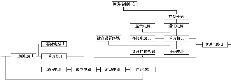
[0022] like figure 1 As shown, the underground locomotive positioning system based on infrared communication technology includes a positioning transmitting device installed on the head of the underground locomotive, a positioning receiving device installed on both sides of the underground roadway, and a communication connection with the positioning receiving device. A control substation, and a dispatch control center communicated with the control substation.

[0023] Wherein, the positioning transmitting device is composed of a single-chip microcomputer I, a power circuit I, an encoding circuit, a modulation circuit, and a storage circuit I respectively connected to the single-chip microcomputer I, a driving circuit connected to the modulation circuit, and a power circuit connected to the driving circuit. Composition of infrared LED emitter. In this embodiment, W79E227 is used for microcontroller I; FM24C04LE M8 is used for storage circuit I; PT2262 is used for encoding circu...


PUM


Abstract

The invention provides an underground locomotive positioning system based on an infrared communication technology. The underground locomotive positioning system is characterized by comprising a positioning transmitting device mounted on the head of an underground locomotive, positioning receiving devices mounted at the two sides of an underground tunnel, a control substation in communication connection with the positioning receiving devices, and a dispatching control center in communication connection with the control substation; the positioning transmitting device is composed of a single chip I, circuits connected with the single chip I, respectively, such as a power circuit I, a coding circuit, a modulation circuit and a storage circuit I, and a drive circuit connected with the modulation circuit and an infrared LED (Light-Emitting Diode) emission head connected with the drive circuit; each positioning receiving device is composed of a single chip II, circuits connected with the single chip II, respectively, such as a power circuit II, a decoding circuit, a communication circuit, a display circuit, a storage circuit II and a keyboard setting terminal, and an infrared receiving circuit connected with the decoding circuit. The underground locomotive positioning system has the advantages of reducing the maintenance amount and the loss amount of the equipment, sufficiently developing the ore carrying efficiency of the underground locomotive, guaranteeing safe underground transportation and improving the mine transportation output.

Description

technical field [0001] The invention relates to an underground locomotive positioning technology, in particular to an underground locomotive positioning system based on infrared communication technology. Background technique [0002] Since 2005, the output of domestic non-coal mines has increased year by year, and small mining areas have gradually been integrated into large and medium-sized mines. And with the gradual reduction of open-pit mining, underground mining has gradually increased. The output of a single mine has increased significantly, and the use of tramcars to transport ore rocks has become the choice of most mines. However, the current transportation capacity of tram locomotives has been unable to reach the ore output level, thus restricting the total output of underground mines and becoming an intermediate bottleneck in the entire process. To maximize the transportation effect, it is particularly important to rationally allocate locomotive transportation seq...

Claims


Application Information

Patent Timeline
IPC IPC(8): B61L25/02G08C23/04
Inventor 王奇张爽刘亮梁吉胜
Owner 中冶北方(大连)工程技术有限公司
Learn More