Methane tank with novel structure

A new type of structure and biogas digester technology, applied in the field of biogas digesters, can solve problems such as complex structure, poor heat preservation, and increased cost, and achieve the effects of improving fermentation efficiency, avoiding safety hazards, and improving repair efficiency

Inactive Publication Date: 2014-10-01
何跃超
View PDF6 Cites 6 Cited by
  • Summary
  • Abstract
  • Description
  • Claims
  • Application Information

AI Technical Summary

Problems solved by technology

There are also some biogas digesters that add a stirring mechanism to achieve stirring, which increases the cost and is not conducive to widespread promotion; however, the structure of this type of biogas digester is complicated during construction, and the airtightness of the gas storage chamber also needs to be considered
It is difficult to discharge slag from the biogas digester. Due to unreasonable design of the bottom of the fermentation room, etc., the bottom of the biogas digester is prone to dead angles. After one to two years of use, the biogas residue often fills the fermentation room, and the The feces in the dead corner must be discharged manually, which is not conducive to the continuous use of gas by users, and it is easy to cause poisoning safety incidents when entering the biogas digester
In addition, because the fermentation liquid in the tank is in a static state for a long time, the surface of the fermentation tank is easy to crust. The general method is to add a stirring mechanism or manual stirring in the fermentation tank, but the structure of the additional stirring mechanism is complicated and the cost is high: 3. The existing biogas digesters are due to The design does not consider the largest gas storage space, and the setting of the manure inlet and manure outlet is based on experience. Usually, the gas is easily discharged from the overflow port or the manure inlet due to the manure inlet. Poor heat preservation and low gas production In winter, the gas production of biogas will be affected by the temperature, resulting in a decrease in gas production. This requires the main tank to have better thermal insulation. The existing biogas tanks, due to reasons such as the structural design of the main tank and the unreasonable selection of pouring materials, are often As a result, the sealing and heat preservation of the main pool are poor, and the gas production is small, which brings inconvenience to people
[0004] Moreover, in the existing biogas digesters, the safety of the main pond has always been a concern for everyone. During the process of fermenting and producing biogas in the main pond, the pressure in the main pond will gradually increase. The port can be used to balance the pressure of the gas in the main tank, but there is still the possibility that the port will be blocked by dung. Even if a safety valve is installed on the exhaust pipe, the normal operation of the safety valve is limited. The key, once the safety valve fails, the pressure of the biogas will cause the main tank to explode, causing serious consequences
[0005] In view of the above problems in existing biogas digesters, it can be seen from this that it is an urgent problem to provide a biogas digester with constant pressure, convenient slag discharge, no crusting and large gas production

Method used


Image

  • Methane tank with novel structure
  • Methane tank with novel structure
  • Methane tank with novel structure

Examples


Embodiment Construction

[0025] Below in conjunction with accompanying drawing and specific embodiment the present invention will be described in further detail:

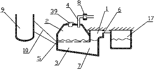
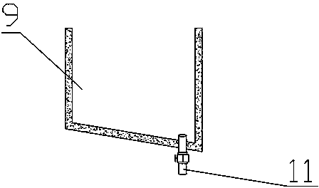
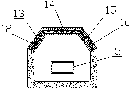
[0026] Such as figure 1 , Figure 4 As shown, a biogas digester with a new structure includes a main pool and a hydraulic room 1. The main pool is composed of a gas storage room 2 and a fermentation tank 3. The top of the gas storage room 2 is provided with an air guide pipe 4. One side of the main pool is There is a manure inlet 5, and the other side communicates with the water pressure room 1; the water pressure room 1 is provided with an overflow port 6, and the manure inlet 5 is located on the side wall of the fermentation tank 3; between the fermentation tank 3 and the water pressure room 1 The excrement outlet 7 is arranged in the room, the height of the excrement outlet 7 is 1 meter, and the width of the water pressure room 1 is 1.2 meters. The excrement outlet 7 is located on the other side wall of the fermentation tank 3; Located...


PUM

PropertyMeasurementUnit
pore sizeaaaaaaaaaa
angleaaaaaaaaaa
angleaaaaaaaaaa

Abstract

The invention discloses a methane tank with a novel structure, which comprises a main tank and a water pressure chamber, wherein the main tank comprises a methane storage room and a fermentation tank, a methane guide pipe is arranged at the top of the methane storage chamber, an excrement inlet is formed in one side of the main tank, and the other side of the main tank is communicated with the water pressure room; an overflow opening is formed in the water pressure chamber, and the excrement inlet is formed in the sidewall of the fermentation tank; an excrement outlet is formed between the fermentation tank and the water pressure chamber, and the excrement outlet is located in the other sidewall of the fermentation tank; the upper edge of the excrement inlet and the top end of the excrement outlet are on the same horizontal line; the bottom of the fermentation tank downwards inclines to the water pressure chamber from the sidewall, where the excrement inlet is located in, and extends to the sidewall where the overflow opening of the water pressure chamber is located in; an excrement dreg drainage channel with a concave semi-spherical cross section is arranged at the bottom of the fermentation tank; the whole methane storage chamber takes the shape of a trapezoid wider in upper part and narrow in lower part, the upper edge of the excrement inlet is arranged at the bottom end of the sidewall of the methane storage chamber, the methane guide pipe is located at the top of the trapezoid and provided with a safety valve. The invention aims to provide the methane tank with the novel structure, which is constant in pressure, convenient for discharging dreg, low in probability of incrustation and high in methane output.

Description

technical field [0001] The invention belongs to the technical field of biogas pits, and in particular relates to a biogas pit with a novel structure. Background technique [0002] Biogas is a kind of renewable bioenergy, which is easy to produce and use. Biogas slurry and biogas residue are also high-quality fertilizers for agricultural production, which can reduce the amount of chemical fertilizers, reduce forest felling, improve the ecological environment, and can also increase farmers' production and Quality of life, biogas is also widely used in the vast rural areas. At present, the country has formulated corresponding standards for the construction of biogas digesters used in rural areas. Hydraulic biogas digesters are the most popular household biogas digesters in my country. In terms of structure, they usually include biogas digesters with spherical arches and square arches. Biogas digesters, biogas digesters usually include a main pool and a water pressure room, the ...

Claims


Application Information

Patent Timeline
Patent Type & Authority Applications(China)
IPC IPC(8): C12M1/107C02F11/04
CPCC12M21/04C12M23/36C12M29/14C12M29/20C12M41/12C12M45/04Y02E50/30
Inventor 何跃超
Owner 何跃超
Why Eureka
Try Eureka