
Centrifugal model test wave cyclic loading simulating device and testing method thereof

A technology of centrifugal model test and simulation equipment, which is applied in the direction of impact test, machine/structural component test, measuring device, etc. It can solve the problem that the wave force cannot be simulated for a long time, the existing technology is difficult to achieve accurate control, and the unfavorable geotechnical centrifugal model layout and other issues, to achieve the effect of convenient regulation, large amplitude and long duration

Inactive Publication Date: 2014-10-01
NANJING HYDRAULIC RES INST
View PDF3 Cites 5 Cited by
  • Summary
  • Abstract
  • Description
  • Claims
  • Application Information

AI Technical Summary

Problems solved by technology

[0013] The object of the present invention is to provide a kind of centrifugal model test wave cyclic load simulation equipment, aiming at solving the following key problems under the high gravity acceleration field of the centrifuge: 1, the prior art can only simulate waves with equal amplitudes of wave pressure and wave suction ; 2. In the existing technology, the wave force needs to be applied by contacting the model through the connecting device. The connecting device changes the original shape of the model and adds an additional vertical force; 3. The existing technology can only simulate the wave force of a small magnitude ; 4, the existing technology is not conducive to the layout of the geotechnical centrifugal model; 5, the existing technology cannot simulate the wave force for a long time; 6, the existing technology is difficult to achieve precise control

Method used


Image

  • Centrifugal model test wave cyclic loading simulating device and testing method thereof

Examples


Embodiment 1

[0040] Example 1 - Geotechnical centrifuge model test research of box-type foundation breakwater.

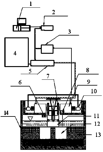
[0041] See figure 1 As shown, the equipment consists of three parts: control part, drive part and output part. The control part is composed of industrial computer, control software, data acquisition card, signal conditioning and adapter, which is used to issue instructions, receive signals from the drive part and output part, and control the characteristic values ​​of the simulated wave force (amplitude, frequency, Wave pressure to wave suction ratio, action time); the driving part includes the driving power supply and the driving power amplifier; the output part includes the exciter, laser displacement sensor, force sensor and armature. In the figure, industrial computer and its control software 1, acquisition card 2, signal conditioning and transfer 3, driving power supply 4, driving power amplifier 5, horizontal displacement laser displacement sensor 6, armature 7, settlemen...


PUM


Abstract

The invention provides a centrifugal model test wave cyclic loading simulating device and a testing method thereof. The simulating device is composed of a control part, a drive part and a force output part. An industrial personal computer of the control part is connected with a signal conditioning part through a data collecting card and is connected with a drive power amplifier through an adaptor. A drive power source of the drive part is connected with two exciters through the drive power amplifier. The two exciters of the force output part generates a wave acting force which is exerted to a research target in a non-contact mode through an armature hung on the center of the lower portion of a top cover of a model casing. The two exciters are provided with a horizontal displacement laser displacement sensor and a settling laser displacement sensor respectively. A force sensor is mounted in each exciter, and the output ends of all the sensors are connected with the industrial personal computer. The simulating device can simulate waves which are large in force amplitude and have the waveform being a sine wave (half-wave), can simulate wave pressures and wave suction forces with any proportion, and is long in duration; wave force can be conveniently regulated and controlled, arrangement of geotechnical centrifugal models is facilitated, operation is safe, and precise control is achieved.

Description

technical field [0001] The present invention relates to an auxiliary device applied to a geotechnical centrifuge, in particular to a device that can be used to simulate the centrifugal model test of the working condition of wave circulation, and is especially suitable for carrying out offshore engineering structures such as docks and breakwaters and drilling platforms. The test simulation of shore engineering structures is used to study the deformation and stability of structures and foundations under the action of waves or storm surges. Background technique [0002] Both offshore engineering and offshore engineering have always been affected by wave action, and there are many strong and long-lasting wave actions such as storm surges. With the great development of society and economy, in offshore engineering, the level of wharf is getting bigger and bigger, and the breakwater is getting farther and farther away from the coast; the development of offshore oil and gas resource...

Claims


Application Information

Patent Timeline
IPC IPC(8): G01M7/08
Inventor 蔡正银王志选徐光明顾行文任国峰黄英豪关云飞徐惠李嫦玲曹永勇
Owner NANJING HYDRAULIC RES INST
Learn More