
An automatic load shedding system and method for ultra-high voltage long-distance transmission line faults

A line fault and load shedding technology, applied in the direction of electrical program control, comprehensive factory control, comprehensive factory control, etc., can solve problems such as difficult to avoid switching off orders, heavy operations by operators, and fire extinguishing of units, so as to reduce hardware investment cost, improve system stability, and reduce operational intensity

Inactive Publication Date: 2017-02-15
大唐阳城发电有限责任公司
View PDF10 Cites 0 Cited by
  • Summary
  • Abstract
  • Description
  • Claims
  • Application Information

AI Technical Summary

Problems solved by technology

After the coal mill is artificially removed, the coordination and adjustment in this special working condition are not good, the load of the unit cannot be reduced quickly, but there will be load fluctuations, and the operating personnel usually have to switch the control mode of the unit to manual control
Therefore, the operating personnel have a large amount of operations, and the control is difficult, and the rapid drop rate cannot meet the dispatching requirements, and it is difficult to avoid the switching order under the dispatching; possibility of
For example, when unit #2 quickly drops the load once, the fuel of the unit decreases too quickly, causing the unit to extinguish the fire
[0006] When the line fails, if the load is reduced too slowly and exceeds the specified time, the dispatcher will order an emergency shutdown of the unit; if there is no fast automatic load reduction device, if the load is reduced too quickly or the personnel operate improperly, there is a high probability that the unit will not stop for fire fighting

Method used


Image

  • An automatic load shedding system and method for ultra-high voltage long-distance transmission line faults

Examples


Embodiment Construction

[0033] The following describes the ultra-high voltage remote transmission line fault automatic load shedding system and its method according to the embodiments of the present invention with reference to the accompanying drawings.

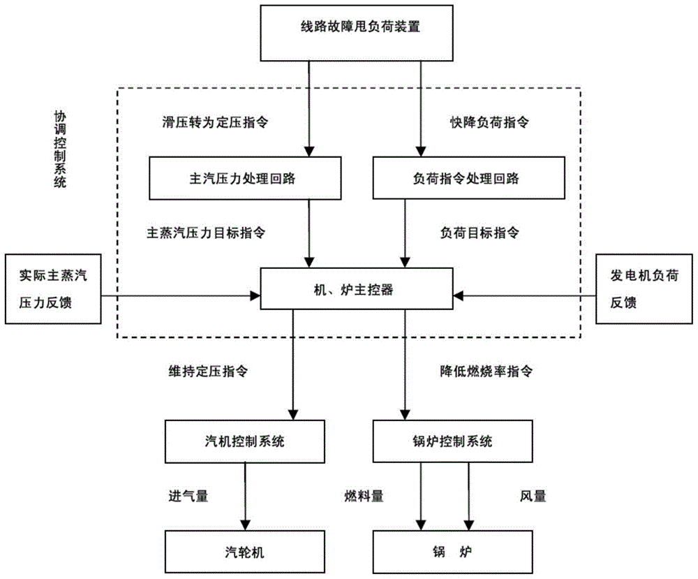
[0034] figure 1 It is a structural schematic diagram of an ultra-high voltage long-distance transmission line fault automatic load shedding system according to an embodiment of the present invention.

[0035] like figure 1 As shown, the line failure unit automatic load shedding system includes: line failure load shedding device, coordination control system, boiler control system, steam turbine control system, boiler, steam turbine.

[0036] The line fault load shedding device includes a start button. When the start button is pressed, the line fault automatic load shedding function will be triggered. The line fault load shedding device will automatically generate a line fault quick load reduction command and a sliding Commands are sent to the coord...


PUM


Abstract

The invention provides an automatic ultrahigh tension long-distance transmission line malfunction load shedding system and method. The ultrahigh tension long-distance transmission line malfunction load shedding system comprises a line malfunction load shedding device, a coordinated control system, a boiler and a steam engine control system. The line malfunction load shedding device generates a line malfunction fast load down instruction and a sliding pressure-constant pressure instruction. A load instruction processing loop and a main steam pressure processing loop in the coordinated control system send a load target instruction and a main steam pressure target instruction to a main engine and boiler controller after receiving the instructions. The main engine and boiler controller sends a boiler combustion ratio reducing instruction to a boiler control system to remove a coal mill and sends a constant pressure maintaining instruction to the steam engine control system, and constant main steam pressure running is carried out until the load of a generator is reduced to the target load. By means of the technical scheme, the load can be automatically, rapidly and stably reduced, the operating strength of operators is relieved, the load can be safely and rapidly reduced to the target value in a unit, the scheduling is prevented from sending an emergency shutdown instruction, and the frequency that the unit is forced to be braked and shut down can be reduced.

Description

technical field [0001] The invention relates to the field of electrical generating set control, in particular to an automatic load shedding system and method for ultra-high voltage long-distance transmission line faults. Background technique [0002] With the large-scale commissioning of the "West-to-East Electricity Transmission" project, ultra-high voltage long-distance transmission lines are responsible for the important task of power plants to transmit electric energy to electric energy users hundreds of kilometers or even thousands of kilometers away. [0003] In recent years, faults and abnormalities in ultra-high voltage long-distance transmission lines have occurred frequently. From 2011 to 2013, a total of 8 incidents occurred in the transmission system of Yangcheng Power Plant that caused the rapid load reduction of the whole plant (note: when a line fails, the system will not start for safety and stability), and system failures mostly occurred in spring and autumn...

Claims


Application Information

Patent Timeline
Patent Type & Authority Patents(China)
IPC IPC(8): G05B19/418
CPCY02P90/02
Inventor 周亚军张国锋南波张文龙乔永成秦敏
Owner 大唐阳城发电有限责任公司
Learn More