Belt sander

An abrasive belt machine and abrasive belt technology, applied in the field of abrasive belt machines, can solve the problems of unstable clamping of parts, poor polishing effect, easy occurrence of fire hazards, etc., and achieve the effects of reducing vibration, prolonging service life and convenient processing.

Inactive Publication Date: 2014-10-08
ZHANGJIAGANG HAIXIN HARDWARE PROD
View PDF7 Cites 3 Cited by
  • Summary
  • Abstract
  • Description
  • Claims
  • Application Information

AI Technical Summary

Problems solved by technology

[0002] With the continuous development of my country's industrialization process, parts polishing is an indispensable part of some parts processing, and its technological development has made great progress. The role of the belt has become irreplaceable. With advanced abrasive belt polishing equipment, metal processing tasks such as surface polishing, circular polishing, dressing polishing and grinding, radius polishing, chamfering and deburring can be satisfactorily completed. The application number is CN201120348692.0, which discloses an abrasive belt machine, including a motor, a coupling, a drive shaft, an abrasive belt, and a transmission shaft. state tension adjustment device, the motor and the driving shaft are connected by a coupling, and the belt support roller is installed on the driving shaft. The machine has the characteristics of simple structure, convenient installation, and wide applicability. However, in the process of polishing the parts, the abrasive belt machine needs to manually hold the processed parts on the abrasive belt machine for polishing, which increases the work intensity of the workers. Factors, the parts are not clamped stably, the polishing effect is poor, and the sparks generated during the polishing process of the parts will fly out due to centrifugal force, which is prone to fire hazards

Method used


Image

  • Belt sander
  • Belt sander

Examples


Embodiment Construction

[0013] In order to make the technical means, creative features, goals and effects achieved by the present invention easy to understand, the present invention will be further described below in conjunction with specific embodiments.

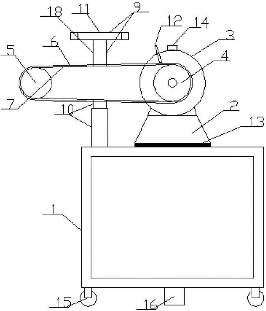
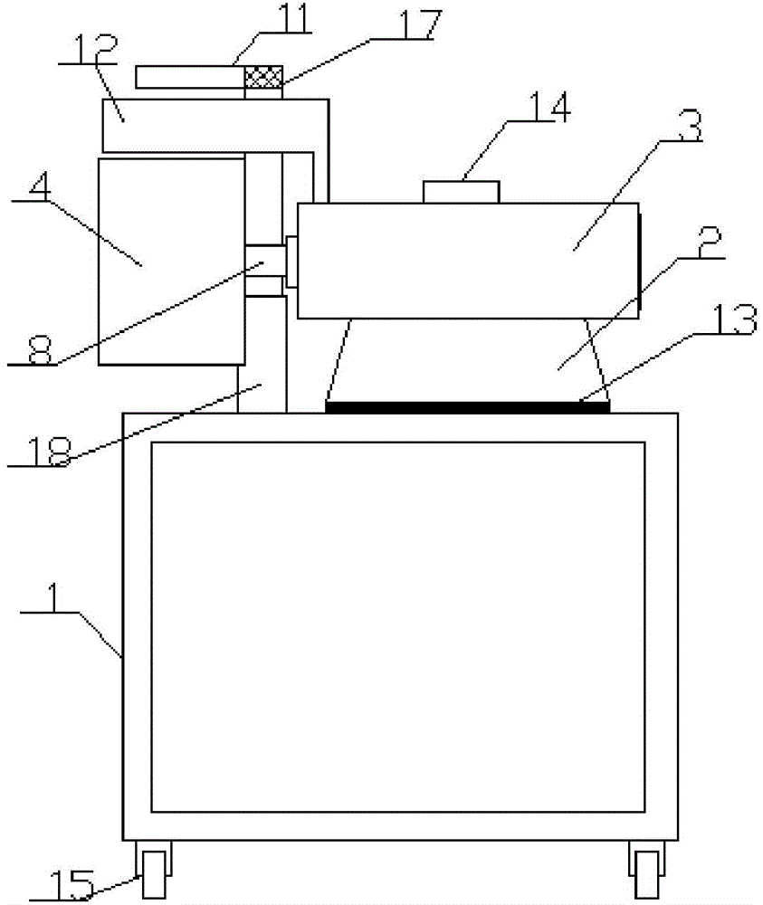
[0014] Such as figure 1 and figure 2 Shown, a kind of abrasive belt machine comprises support 1, base 2, motor 3, abrasive belt wheel 4, driven wheel 5, abrasive belt 6 and abrasive belt housing 7, and described base 2 is connected with support 1, and described motor 3 is set on the base 2, the abrasive belt wheel 4 is connected with the motor 3 through the transmission shaft 8, the abrasive belt wheel 4 is connected with the driven wheel 5 through the abrasive belt housing 7, and the bracket 1 is provided with a clamp 9, The clamp 9 includes a clamp bracket 10 and a clamping part 11, the clamping part 11 is connected with the clamp bracket 10 through a rotating shaft 17, the clamp bracket 10 is composed of two hydraulic rods 18, and the motor 3...


PUM


Abstract

The invention discloses a belt sander and relates to the field of industrial machinery. The belt sander comprises a support, a base, a motor, a sanding belt wheel, a driven wheel, a sanding belt and a sanding belt shell, wherein the base is connected with the support, the motor is arranged on the base, the sanding belt wheel and the motor are connected through a driving shaft, the sanding belt wheel is connected with the driven wheel through the sanding belt shell, and the support is provided with a clamp comprising a clamp support and a clamping part. The clamping part is connected with the clamp support through a rotary shaft, and the clamp support is composed of two hydraulic rods. The motor is provided with an ash damper 2-3mm in thickness, the clamp vertically moves through the hydraulic rods and is rotatable through a rotary shaft, parts can be conveniently polished from various angles, polishing depth of the parts can be adjusted, the support is provided with an ash damping plate capable of stopping sparks generated during polishing from splashing, and fire risk is prevented.

Description

technical field [0001] The invention relates to the field of industrial machinery, in particular to a belt sander. Background technique [0002] With the continuous development of my country's industrialization process, parts polishing is an indispensable part of some parts processing, and its technological development has made great progress. The role of the belt has become irreplaceable. With advanced abrasive belt polishing equipment, metal processing tasks such as surface polishing, circular polishing, dressing polishing and grinding, radius polishing, chamfering and deburring can be satisfactorily completed. The application number is CN201120348692.0, which discloses an abrasive belt machine, including a motor, a coupling, a drive shaft, an abrasive belt, and a transmission shaft. state tension adjustment device, the motor and the driving shaft are connected by a coupling, and the belt support roller is installed on the driving shaft. The machine has the characteristics o...

Claims


Application Information

Patent Timeline
Patent Type & Authority Applications(China)
IPC IPC(8): B24B21/18B24B41/06
CPCB24B21/00B24B21/18B24B41/06B24B55/00
Inventor 刘刚
Owner ZHANGJIAGANG HAIXIN HARDWARE PROD
Why Eureka
Try Eureka