
A system for preparing colloidal crystals and a method for preparing colloidal crystals

A colloidal crystal and injection system technology, applied in crystal growth, chemical instruments and methods, single crystal growth, etc., can solve the problems of long period, difficult preparation of multi-particle size composite colloidal crystals, harsh growth conditions, etc.

Inactive Publication Date: 2016-08-24
JILIN NORMAL UNIV
View PDF8 Cites 0 Cited by
  • Summary
  • Abstract
  • Description
  • Claims
  • Application Information

AI Technical Summary

Problems solved by technology

[0005] The purpose of the present invention is to provide a system for preparing colloidal crystals in order to solve the problems of long cycle, limited growth area, difficult preparation of multi-particle size composite colloidal crystals and harsh growth conditions in the existing colloidal crystal preparation methods. Preparation method of colloidal crystal

Method used


Image

  • A system for preparing colloidal crystals and a method for preparing colloidal crystals
  • A system for preparing colloidal crystals and a method for preparing colloidal crystals
  • A system for preparing colloidal crystals and a method for preparing colloidal crystals

Examples


preparation example Construction

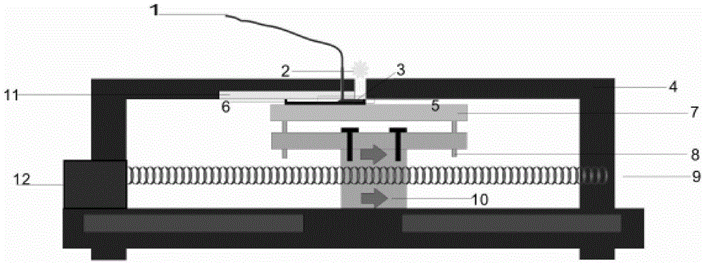
[0038] The present invention also provides a method for preparing colloidal crystals, the method comprising:

[0039] Step 1: Prepare and clean the sample groove 6, fix the sample groove 6 on the metal platform 7, and align the right side of the sample groove 6 with the right side of the polytetrafluoroethylene plate 11;

[0040] Step 2: Turn on the infrared wavelength heat source 2, and wait until the infrared wavelength heat source 2 reaches a stable state, preferably move the infrared wavelength heat source 2 to a distance of 10-15 cm from the sample groove, so that it can irradiate the polytetrafluoroethylene plate 11 and the sample groove 6 The meniscus 3 formed between; the infrared wavelength heat source is preferably an infrared evaporator;

[0041] Step 3: Inject the microsphere solution into the sample groove 6 through the microsphere injection system 1, so that the microsphere solution fills the gap between the sample groove 6 and the right side of the polytetrafluo...

Embodiment 1

[0051] Step 1: prepare and clean the sample groove 6, fix the sample groove 6 on the metal platform 7, and align the right side of the sample groove 6 with the right side of the polytetrafluoroethylene plate 11;

[0052] Step 2: Turn on the infrared evaporator 2, and when the infrared evaporator 2 reaches a stable state, move the infrared evaporator to a distance of 10-15 cm from the sample groove, so that it can irradiate between the PTFE plate 11 and the sample groove 6 The meniscus 3 formed;

[0053] Step 3: Inject 20 ul of polystyrene microsphere solution with a concentration of 10% into the sample groove 6 at an injection rate of 5 μl / min, so that the polystyrene microsphere solution fills the sample groove 6 and the polytetrafluoroethylene plate 11 side gaps;

[0054] Step 4: Turn on the driving motor 12, and the driving motor 12 drives the threaded shaft 9 to drive the metal moving module 10 to move to the right, and at the same time inject polystyrene solution into th...

Embodiment 2

[0059] The difference from Example 1 is that the injection rate is set to 15 μl / min, and the rest of the steps and conditions are the same as in Example 1.

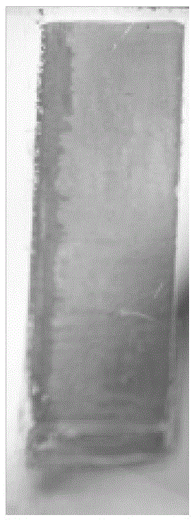
[0060] The experimental results show that when the injection rate is 15 μl / min, the integrity of the ordered colloidal crystal sample formed by the present invention is better, and there are fewer cracks on the surface of the sample, which is less different from the colloidal crystal sample in Example 1. Image 6 The SEM image of the surface of the colloidal crystals prepared in Example 2 of the present invention shows that the polystyrene microspheres of the present invention are regularly arranged and have a high degree of order.


PUM

PropertyMeasurementUnit
particle diameteraaaaaaaaaa

Abstract

The invention provides a system for preparing a colloidal crystal and a method for preparing the colloidal crystal and belongs to the field of preparation methods of colloidal crystals. The system comprises a microsphere injection system, an infrared wavelength heat source, a metal frame, a sample groove, a metal platform, a threaded shaft, a metal movement module, a polyfluortetraethylene plate and a drive motor, wherein the drive motor is arranged at the left end of the metal frame, the threaded shaft is connected to the drive motor, the metal movement module is sleeved on the threaded shaft, the metal movement module is connected to the metal platform, the sample groove is formed in the metal platform, the polyfluortetraethylene plate is fixed to the upper end of the metal frame and is in contact with the sample groove, the drive motor rotates to drive the threaded shaft so as to drive the metal movement module to move right. The invention also provides a method of preparing the colloidal crystal; by virtue of the method, single-particle-size and multi-particle-size colloidal crystal templates can be assembled within a relatively short time range, and the obtained colloidal crystal has controllable thickness and is ordered in a large area.

Description

technical field [0001] The invention belongs to the field of preparation methods of colloidal crystals, and in particular relates to a system for preparing colloidal crystals and a preparation method of colloidal crystals. Background technique [0002] In the 21st century, manipulating photons in the field of photons has become the core research content. Because of its special periodic structure, colloidal crystals can be used as templates to prepare photonic crystals with inverse opal structures, which provides excellent means for the structural design and performance optimization of optical functional materials. . [0003] The existing method commonly used to prepare colloidal crystals is the vertical deposition method, which was first proposed by Nagayama K in 1996. This method is to carry out self-assembly on the substrate, that is, simply dip the substrate vertically into a substrate containing monodisperse microspheres. In the colloidal solution, a meniscus is formed ...

Claims


Application Information

Patent Timeline
Patent Type & Authority Patents(China)
IPC IPC(8): C30B5/00
Inventor 孟祥东鲁铭胡悦李海波于兆亮曲晓慧华杰
Owner JILIN NORMAL UNIV
Learn More