Photovoltaic module adjusting circuit and remote monitoring system

A remote monitoring system and photovoltaic module technology, applied in the field of solar photovoltaic power generation, can solve the problems of inconsistent parameters of photovoltaic cells in the manufacturing process, unable to completely save power loss, difficult to find the maximum power point, etc., to facilitate performance analysis and fault diagnosis, The effect of low loss and low power consumption

Active Publication Date: 2014-10-08
GUANGZHOU INST OF ENERGY CONVERSION - CHINESE ACAD OF SCI
View PDF9 Cites 6 Cited by
  • Summary
  • Abstract
  • Description
  • Claims
  • Application Information

AI Technical Summary

Problems solved by technology

However, although the bypass diodes in parallel avoid the aggravation of the "hot spot effect" and reduce the power loss of solar cells, they cannot completely save the overall string power loss caused by shading.
[0004] Photovoltaic modules are shaded or due to differences in manufacturing processes, which will lead to inconsistent photovoltaic cell parameters
In the photovoltaic module series system, the output power is no longer a single-peak curve, but multiple peaks, and the maximum power tracking algorithm used is difficult to find the actual maximum power point
Photovoltaic modules work under the above conditions, and some power will inevitably be lost

Method used


Image

  • Photovoltaic module adjusting circuit and remote monitoring system
  • Photovoltaic module adjusting circuit and remote monitoring system
  • Photovoltaic module adjusting circuit and remote monitoring system

Examples


Embodiment 1

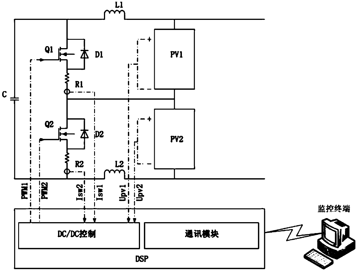
[0042] Such as figure 1 As shown, the electronic components of the regulating circuit include the first photovoltaic component PV1, the second photovoltaic component PV2, the first inductor L1, the second inductor L2, the capacitor C, the first N-MOS field effect transistor Q1, the second N-MOS type field effect transistor Q2, the first resistor R1, the second resistor R2, the first diode D1 and the second diode D2.

[0043] The first photovoltaic component PV1 is connected in series with the second photovoltaic component PV2, and the negative pole of the first photovoltaic component PV1 is connected with the positive pole of the second photovoltaic component PV2.

[0044] The anode of the first photovoltaic module PV1 is connected to one end of the first inductance L1, the other end of the first inductance L1 is connected to the drain of the first N-MOS field effect transistor Q1, and the source of the first N-MOS field effect transistor Q1 One end of the first resistor R1 i...

Embodiment 2

[0059] Such as Figure 11 As shown, the regulator circuit can also apply the topological structure of a buck-boost DC / DC circuit, including an inductor L, a third N-MOS field effect transistor Q3, a fourth N-MOS field effect transistor Q4, and a third diode tube D3, fourth diode D4 and first capacitor C1,

[0060] The positive pole of the first photovoltaic component PV1 is connected to one side of the third N-MOS field effect transistor Q3, and the other side of the third N-MOS field effect transistor Q3 is connected to the negative pole of the first photovoltaic component PV1;

[0061] The positive pole of the second photovoltaic module PV2 is connected to one side of the fourth N-MOS field effect transistor Q4, and the other side of the fourth N-MOS field effect transistor Q4 is connected to the negative pole of the second photovoltaic module PV2;

[0062] One side of the inductor L is connected to the connection point between the third N-MOS field effect transistor Q3 and...


PUM


Abstract

The invention discloses a photovoltaic module adjusting circuit and remote monitoring system. Two adjacent photovoltaic modules connected in series are connected with an adjusting circuit. When one photovoltaic module is overshadowed or is under other non-normal conditions to result in inconsistent voltages of the adjacent photovoltaic modules, the adjusting circuit starts to work and adjusts the voltages of the adjacent photovoltaic modules to make the voltages consistent so as to realize terminal voltage balance and improve the overall output power of the module string. The adjusting circuit is provided with a digital signal processor, a communication module and a monitoring terminal. Voltage, current and temperature state of the photovoltaic modules can be monitored in real time, the state information of the photovoltaic modules can be collected, and any series-connected photovoltaic module which is overshadowed or is under other non-normal conditions can be automatically adjusted. The overall output power of the photovoltaic module string is improved. A controller is high in efficiency and low in loss. The adoption of a graphical monitoring terminal interface enables users to conveniently perform performance analysis and fault diagnosis on a photovoltaic system.

Description

technical field [0001] The invention relates to the technical field of solar photovoltaic power generation, in particular to an adjustment circuit and a remote monitoring system of a photovoltaic module. Background technique [0002] The voltage of the single solar cells is relatively low, and the single solar cells are generally connected in series to make the output voltage meet the load requirements. Photovoltaic modules are generally packaged by combining multiple single solar cells in series and parallel. Photovoltaic modules will produce a "hot spot effect" due to partial shading, that is, the short-circuit current of the shaded solar cells will become smaller, which will limit the output of the series circuit. current. In the module, part of the photogenerated current of the normal non-shading solar cell makes its own PN junction positively biased, forming a positive bias; in the circuit, the shading solar cell is subjected to reverse bias, and the shading solar cell...

Claims


Application Information

Patent Timeline
Patent Type & Authority Applications(China)
IPC IPC(8): H02S40/36H02J13/00
CPCY02E10/50Y04S10/40
Inventor 吴昌宏舒杰张继元戴志威吴志锋关锐奇沈玉樑
Owner GUANGZHOU INST OF ENERGY CONVERSION - CHINESE ACAD OF SCI
Why Eureka
Try Eureka