Gradual depth method for removing metal ion impurity from nickel anode electrolyte
A technology of impurity metal ions and electrolyte, applied in the field of nickel production, can solve the problem of inability to deeply remove impurity ions iron and lead, and achieve the effect of satisfying production requirements and simple process
- Summary
- Abstract
- Description
- Claims
- Application Information
AI Technical Summary
Problems solved by technology
Method used
Image

Examples
Embodiment 1
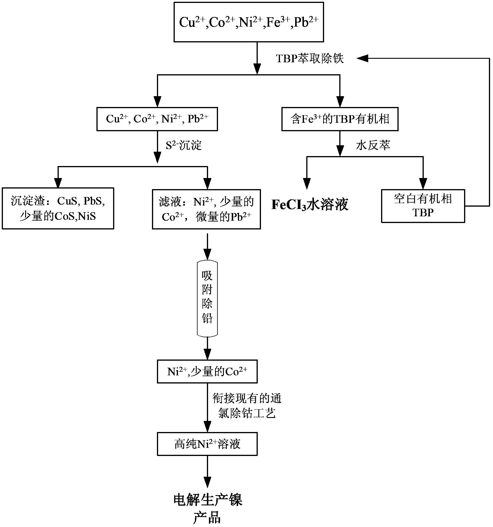
[0046] (1) Tributyl phosphate (TBP) was used as the extraction agent, sulfonated kerosene was used as the diluent, and Fe was removed by two-stage countercurrent cascade extraction 3+ , to obtain the feed liquid composed as shown in Table 2, the organic phase is washed and stripped with water, and all the Fe in the nickel electrolyte is recovered 3+ , the organic phase is recycled;
[0047] (2) Use nickel carbonate to adjust the pH of the solution to 1, then add sodium sulfide to form CuS, PbS and CoS precipitates, and remove all Cu in the system 2+ , most of the Pb 2+ and a small amount of Co 2+ , obtain the feed liquid of composition as shown in table 3;
[0048] (3) Use 25ml of weakly basic anion resin D301 to adsorb for 1h to remove Pb 2+ , to obtain a feed liquid composed as shown in Table 4, and adsorbed Pb 2+ The resin is regenerated using NaOH solution;
[0049] (4) Chlorine removal of Co 2+ , to obtain a nickel electrolyte.
Embodiment 2
[0051] (1) Dimethylheptane methyl phosphate (P350) was used as the extractant, n-heptane was used as the diluent, and Fe was removed by 2-stage countercurrent cascade extraction 3+ , to obtain the feed liquid composed as shown in Table 2, the organic phase is washed and stripped with water, and all the Fe in the nickel electrolyte is recovered 3+ , the organic phase is recycled;
[0052] (2) Adjust the pH of the solution to 0.5, then add sodium sulfide to form CuS, PbS and CoS precipitates, and remove all Cu in the system 2+ , most of the Pb 2+ and a small amount of Co 2+ , obtain the feed liquid of composition as shown in table 3;
[0053] (3) Use 25ml of weakly basic anion resin D318 to adsorb for 2h to remove Pb 2+ , to obtain a feed liquid composed as shown in Table 4, and adsorbed Pb 2+ The resin is regenerated using HCl solution;
[0054] (4) Chlorine removal of Co 2+ , to obtain a nickel electrolyte.
Embodiment 3
[0056] (1) Using butyl dibutyl phosphonate (DBBP) as the extractant, n-hexane as the diluent, and two-stage countercurrent cascade extraction to remove Fe 3+ , to obtain the feed liquid composed as shown in Table 2, the organic phase is washed and stripped with water, and all the Fe in the nickel electrolyte is recovered 3+ , the organic phase is recycled;
[0057] (2) Use nickel carbonate to adjust the pH of the solution to 3, then add nickel sulfide to form CuS, PbS and CoS precipitates, and remove all Cu in the system 2+ , most of the Pb 2+ and a small amount of Co 2+ , obtain the feed liquid of composition as shown in table 3;
[0058] (3) Use 25ml of weakly basic anion resin D315 to adsorb for 1.5h to remove Pb 2+ , to obtain a feed liquid composed as shown in Table 4, and adsorbed Pb 2+ The resin is regenerated using HCl solution;
[0059] (4) Chlorine removal of Co 2+ , to obtain a nickel electrolyte.
PUM
 Abstract
Description
Claims
Application Information
 - R&D
- Intellectual Property
- Life Sciences
- Materials
- Tech Scout
- Unparalleled Data Quality
- Higher Quality Content
- 60% Fewer Hallucinations
Browse by: Latest US Patents, China's latest patents, Technical Efficacy Thesaurus, Application Domain, Technology Topic, Popular Technical Reports.
© 2025 PatSnap. All rights reserved.Legal|Privacy policy|Modern Slavery Act Transparency Statement|Sitemap|About US| Contact US: help@patsnap.com