A fluorescence ratio measurement system and method

A measurement system and fluorescence technology, applied in the field of fluorescence analysis, can solve the problems of being easily affected by the change of light source intensity and the sensitivity of the instrument, the time-consuming measurement process, the high investment cost, etc., achieving good practical value and economic value, and wide application fields , the effect of low cost measurement system

Inactive Publication Date: 2017-01-04
JIANGSU UNIV
View PDF7 Cites 0 Cited by
  • Summary
  • Abstract
  • Description
  • Claims
  • Application Information

AI Technical Summary

Problems solved by technology

[0003] In the fluorescence ratio method, the ratio of the intensities of two fluorescence emission peaks at different positions is usually obtained. The following two methods are usually used: The first method is to switch the fluorescence filter in front of a single photoelectric sensor (such as a CCD) so that the central wavelengths are respectively Corresponding to two different fluorescence emission peaks, the corresponding fluorescence ratio value is calculated from the intensities of the two different fluorescence emission peaks collected twice; this method is vulnerable to the light source when a single photoelectric sensor collects the intensity of a single fluorescence emission peak. Intensity changes and sensitivity of the instrument are affected, and the entire measurement process takes a long time
The second method is to use two photoelectric sensors (such as CCD), and the central wavelength of the fluorescent filter placed in front of each photoelectric sensor corresponds to a different fluorescent emission peak, and the two different fluorescent lights collected by the two photoelectric sensors at the same time The intensity of the emission peak calculates the corresponding fluorescence ratio value; although the second method overcomes the influence of the light source intensity change on the fluorescence ratio in the first method, it requires the use of two photoelectric sensors, and high-performance scientific-grade refrigeration is commonly used in fluorescence intensity image acquisition CCD, dual-CCD measurement system not only needs to consider the high investment cost of the system, but also needs to consider the influence of the difference in the response performance of the two CCDs on the measurement; in addition, the two fluorescence intensity images used for the calculation of the fluorescence ratio in the second method come from two For photoelectric sensors, before calculating the fluorescence ratio, image correlation processing must be performed on the selected fluorescence ratio calculation area on the two fluorescence intensity images to ensure that the fluorescence ratio calculation area on the two fluorescence intensity images corresponds to the same area on the test sample. The target area, visible, complex and time-consuming image-related processing operations are also one of the factors to be considered in the second method

Method used


Image

  • A fluorescence ratio measurement system and method

Examples


Embodiment Construction

[0016] The technical solutions of the present invention will be further described in detail below in conjunction with the accompanying drawings and specific embodiments.

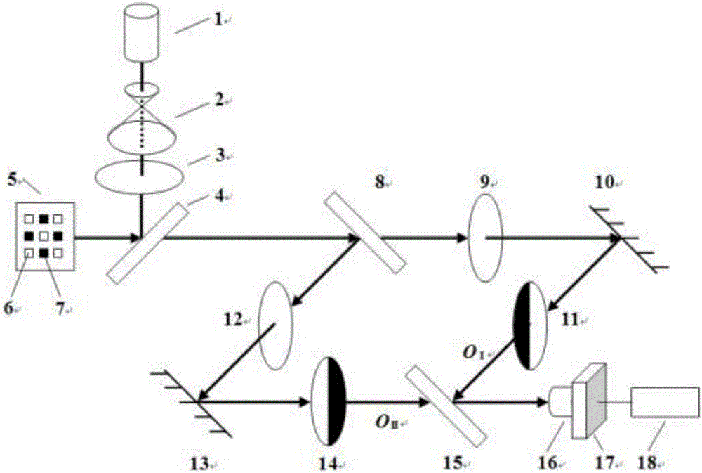
[0017] refer to figure 1 , a fluorescence ratio measurement system, including a light source 1 for providing excitation light waves, a collimating beam expander lens group 2, an excitation filter 3, a dichroic beam splitter 4, and a sample 5 for generating stimulated emission of fluorescence The first fluorescent dye 6 and the second fluorescent dye 7, including the fluorescent dye 6 and the fluorescent dye 7 are simultaneously excited with the same wavelength, or the fluorescent dye 6 or the fluorescent dye 7 is first excited with a single wavelength, and then the fluorescent dye 6 or the fluorescent dye is excited. The stimulated emission light of 7 excites the dye 7 or dye 6, the first beam splitter 8 and the second beam splitter 15 for light splitting, the first emission filter 9 for obtaining the first ...


PUM


Abstract

The invention discloses a fluorescence ratio measuring system and method. The fluorescence ratio measuring system is used for acquiring a fluorescence signal when a sample is subjected to stimulated emission based on a typical Mach-Zehnder interferometer light path, the fluorescence signal when the sample is subjected to stimulated emission is decomposed into a transmission light beam and a reflection light beam by a spectroscope in the light path, an interference filter and a complementary clear grating are respectively placed in propagation light paths of two light beams, and a single CCD (Charge Coupled Device) simultaneously acquires fluorescence signal intensities with different emission wavelengths of two light beams. A standard curve between a to-be-tested physical quantity and intensity ratios of the fluorescence signals with different emission wavelengths of the two light beams is established through a standard sample group, and further the to-be-tested physical quantity of a sample is determined by applying the pre-established standard curve according to the fluorescence ratio measured from the to-be-tested sample. The fluorescence ratio measuring method is suitable for all measuring systems based on a fluorescence ratio, comprising conventional two times of acquisition by the single CCD and simultaneous acquisition of the fluorescence ratio by two CCDs. The fluorescence ratio measuring system and method are widely applied to the fields of measuring a pH value, a temperature, a thickness and the like.

Description

technical field [0001] The invention belongs to the technical field of fluorescence analysis, and in particular relates to a fluorescence ratio measurement system and method. Background technique [0002] Due to the advantages of good selectivity, high sensitivity, convenience and simplicity, accuracy and speed, and wide linear range, fluorescence analysis technology has been widely used in the fields of biology, chemistry, medicine, and environmental monitoring. Fluorescence analysis is based on the relationship between the fluorescence intensity of a single fluorescence emission peak and the physical quantity to be measured (such as the pH value of the solution, the temperature of the sample, and the optical path in the sample) to analyze and detect the physical quantity to be measured, but this analysis method is sensitive to environmental factors , susceptible to interference from external factors. The fluorescence ratio method uses the ratio of the intensity of two flu...

Claims


Application Information

Patent Timeline
Patent Type & Authority Patents(China)
IPC IPC(8): G01N21/64
Inventor 花世群阮小霞骆英
Owner JIANGSU UNIV
Why Eureka
Try Eureka