Wind-induced vibration piezoelectric generator

A wind-induced vibration and generator technology, applied in generators/motors, piezoelectric effect/electrostrictive or magnetostrictive motors, electrical components, etc., can solve the problems of low power density, complex structure, low voltage output, etc. , to achieve the effect of increasing output voltage, increasing energy density and simple structure

Inactive Publication Date: 2014-10-22
XIDIAN UNIV
View PDF4 Cites 39 Cited by
  • Summary
  • Abstract
  • Description
  • Claims
  • Application Information

AI Technical Summary

Problems solved by technology

[0005] The purpose of the present invention is to overcome the problems of complex structure, low

Method used


Image

  • Wind-induced vibration piezoelectric generator
  • Wind-induced vibration piezoelectric generator
  • Wind-induced vibration piezoelectric generator

Examples


Embodiment 1

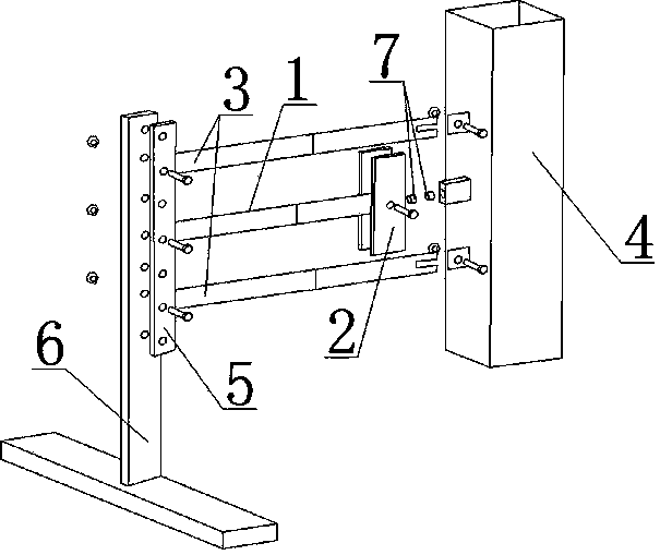
[0034] In order to solve the problems of the existing wind-induced vibration piezoelectric generator with complex structure, low voltage output and low power density, the wind-induced vibration piezoelectric generator provided by the present invention is as follows: figure 1 As shown, it includes a bracket 6, a piezoelectric cantilever beam, a mass block 2, a bluff body 4, and a permanent magnet 7; the piezoelectric cantilever beam includes an inner beam 1 and an outer beam 3, and one end of the outer beam 3 is provided with a through hole , is fixedly connected with the bracket 6 by bolts, the other end (free end) is provided with a card slot, and is fixedly connected with the bluff body 4 by bolts, one end of the inner beam 1 is provided with a through hole, and is fixedly connected with the bracket 6 by bolts, and the other One end (free end) is provided with a card slot and is fixedly connected with the mass block 2 by bolts.

[0035] In this embodiment, there are two oute...

Embodiment 2

[0043] The difference from the above embodiment is that the number of outer beams 3 and inner beams 1 varies; the number of outer beams 3 is not necessarily limited to 2, but can also be 1 or 3. The bluff body 4 vibrates together and outputs a voltage under the excitation vibration; similarly, the inner beam 1 is not limited to one; its characteristic is that the wind load acts on the bluff body 4, forming a Karman vortex street in the wake, and Karman vortex street action Due to the inner beam 1, the inner beam 1 vibrates, and the inner beam 1 outputs a voltage under the vibration excitation, and at the same time, the quantity of the mass block 2 and the permanent magnet 7 also changes correspondingly with the change of the number of the inner beam 1 .

[0044] In this embodiment, corresponding dimensions can be adopted according to specific application requirements. Table 1 below lists a set of design parameters of the entire piezoelectric generator. The sheet metal beams i...


PUM

PropertyMeasurementUnit
Magnetic momentaaaaaaaaaa

Abstract

The invention belongs to the technical field of renewable energy sources and power generation, and especially relates to a wind-induced vibration piezoelectric generator which is suitable for low-power-consumption electronic devices, such as microsensors, micro-performers, minisize signal processors and emitters and the like, which need to obtain energy from external environment to carry out energy supplement. The piezoelectric generator is formed by three piezoelectric cantilever beams, a quality block, a fluid-stopping body, permanent magnets, a clamping plate, a support and a bridge rectifier circuit. According to the piezoelectric generator, the principle of galloping of the wind-induced fluid-stopping body and the piezoelectric effect are utilized to enable the wind energy to be converted into electric energy, and the converted electric energy is then stored in an energy storage component through a bridge rectifier. The coupling effect between the inner beam and the outer beam is utilized to enable the vibration energy of the outer energy to be transmitted to the inner beam, thereby not only preventing the outer beam from causing rupture damage due to large deformation, but also improving the output voltage of the inner beam. The piezoelectric generator is simple in structure, low in cost, high in power density, and is suitable for auxiliary power supply of the wireless sensors and low-power-consumption devices.

Description

technical field [0001] The invention belongs to the technical field of renewable energy and power generation, and in particular relates to a wind-induced vibration piezoelectric generator, which is suitable for micro-sensors, micro-actuators, micro-signal processors and transmitters, etc., which need to capture energy from the external environment for energy supplementation. low power electronics. Background technique [0002] At present, various low-power devices such as micro-sensors, micro-actuators, micro-signal processors and transmitters continue to emerge. When the device is miniaturized, the size of the energy device determines the size of the entire system. Without miniaturized energy equipment to provide continuous energy, micro-miniature devices will be difficult to take advantage of their miniaturization, and even lose their original meaning of miniaturization. If efficient micro-energy can be produced to replace battery energy with limited life, many difficult...

Claims


Application Information

Patent Timeline
IPC IPC(8): H02N2/18
Inventor 樊康旗车晓寰晁锋波
Owner XIDIAN UNIV
Why Eureka
Try Eureka