
Scrap accumulation prevention type semi-automatic reciprocating polishing device

A polishing device, semi-automatic technology, applied in grinding/polishing safety devices, grinding/polishing equipment, grinding racks, etc., can solve the problems of damaged plane accuracy, low processing efficiency, high work intensity, etc., to ensure roughness degree, preventing rational changes, and protecting the effect of the workpiece

Inactive Publication Date: 2014-10-29
SUZHOU TAKESHENG ELECTRONICS SCI & TECH
View PDF7 Cites 8 Cited by
  • Summary
  • Abstract
  • Description
  • Claims
  • Application Information

AI Technical Summary

Problems solved by technology

[0002] In the existing mechanical processing process, in order to reduce the surface roughness of the workpiece, the processed workpiece is polished. However, in the existing enterprises, the polishing method is that the employees hold the workpiece with bare hands and paste it on the running disc for polishing or polishing. Pushing the plane with a whetstone by hand, this traditional polishing method is barely used for products with low processing requirements and light weight, but when the workpiece to be polished is large and has high requirements on the end surface, there are the following defects : 1. At present, most of the operators in enterprises are female workers over 40 years old. Limited by physical strength factors, they cannot lift large parts such as the pump body and polish them on the polishing disc, resulting in high work intensity; 2. In the past, the workpiece was put on the work On the stage, workers use manual polishing, which is very likely to cause the edge of the workpiece to collapse and damage the original precision of the plane, resulting in a high scrap rate of the product; Batch production, resulting in low processing efficiency; 4. Long-term operation leads to deformity of the back of the operator's hand

Method used


Image

  • Scrap accumulation prevention type semi-automatic reciprocating polishing device
  • Scrap accumulation prevention type semi-automatic reciprocating polishing device

Examples


Embodiment Construction

[0012] The following will clearly and completely describe the technical solutions in the embodiments of the present invention with reference to the accompanying drawings in the embodiments of the present invention. Obviously, the described embodiments are only some, not all, embodiments of the present invention. Based on the embodiments of the present invention, all other embodiments obtained by persons of ordinary skill in the art without making creative efforts belong to the protection scope of the present invention.

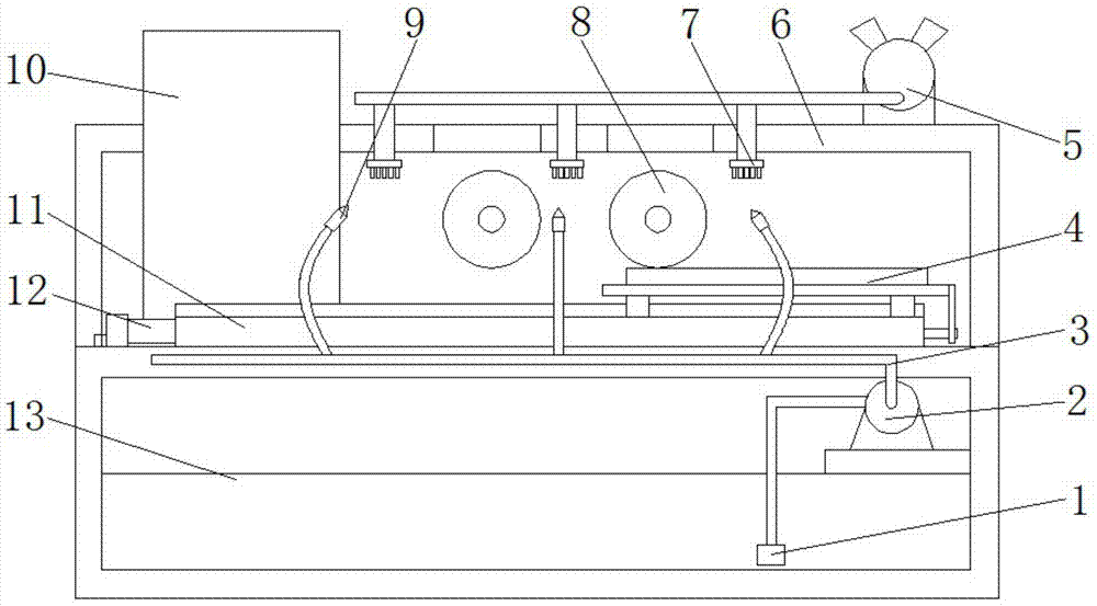
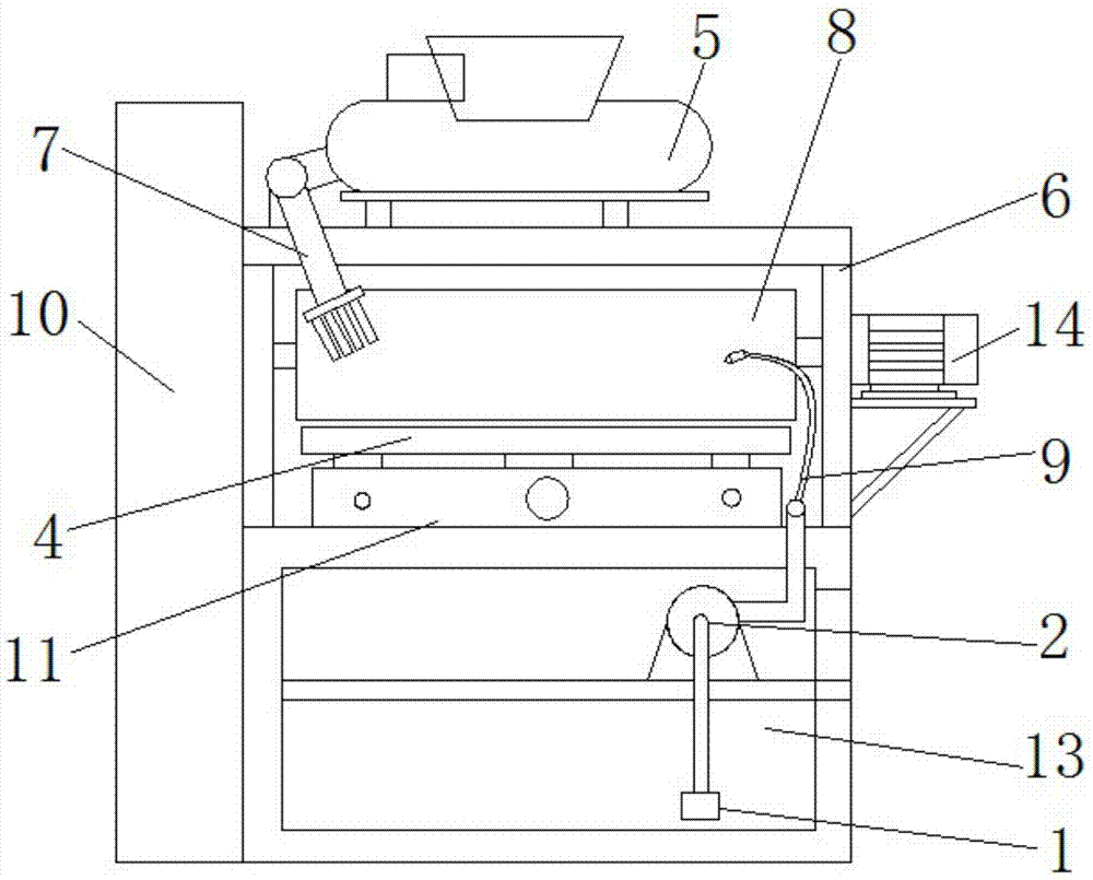
[0013] see Figure 1~2 , in the embodiment of the present invention, an anti-chip semi-automatic reciprocating polishing device includes a frame 6, and the frame 6 is provided with a screw assembly 11, and the screw assembly 11 is connected to a feed motor 12 to drive the screw assembly 11. The screw mandrel assembly 11 is provided with a workbench 4, and above the workbench 4 is provided with a polishing assembly 8. The power source of the polishing assembly ...


PUM


Abstract

The invention discloses a scrap accumulation prevention type semi-automatic reciprocating polishing device which comprises a rack. The rack is provided with a screw rod assembly, the screw rod assembly is connected with a feed motor to drive the screw rod assembly, and the screw rod assembly is provided with a workbench. A polishing assembly is arranged above the workbench, a plurality of jet heads are arranged above the rack, and the jet heads are communicated with one another and then connected with an air pump. The workbench makes reciprocating movement on the screw rod assembly, so that workpieces on the workbench are subjected to reciprocating polishing under the polishing assembly, the jet heads are used for timely cleaning up scraps such as iron sand on the workpieces, and the scraps are prevented from scratching machining surfaces. Meanwhile, a cooling liquid nozzle is connected with a water pipe through a metal hose so that the polished surfaces can be timely cooled, and physical change on the surfaces of the workpieces caused by high temperature is prevented. Accordingly, the roughness of the surfaces of the polished workpieces is guaranteed, meanwhile, the scraps such as the iron sand generated by polishing can be prevented from damaging the surfaces of the workpieces, and the workpieces are effectively protected.

Description

technical field [0001] The invention relates to a polishing device, in particular to an anti-dust collection type semi-automatic reciprocating polishing device. Background technique [0002] In the existing mechanical processing process, in order to reduce the surface roughness of the workpiece, the processed workpiece is polished. However, in the existing enterprises, the polishing method is that the employees hold the workpiece with bare hands and paste it on the running disc for polishing or polishing. Pushing the plane with a whetstone by hand, this traditional polishing method is barely used for products with low processing requirements and light weight, but when the workpiece to be polished is large and has high requirements on the end surface, there are the following defects : 1. At present, most of the operators in enterprises are female workers over 40 years old. Limited by physical strength factors, they cannot lift large parts such as the pump body and polish them...

Claims


Application Information

Patent Timeline
IPC IPC(8): B24B55/06
CPCB24B41/02B24B55/00B24B55/02
Inventor 费志瑾
Owner SUZHOU TAKESHENG ELECTRONICS SCI & TECH
Learn More