

Rubbish incineration and waste gas purification device and feeding machine thereof
A waste gas purification device and waste incineration technology, applied in the field of feeder, can solve the problems of uneven waste incineration, complicated engineering, low combustion efficiency, etc., to eliminate tiny dust and harmful bacteria, prevent secondary pollution, and long-term work damage Effect
- Summary
- Abstract
- Description
- Claims
- Application Information
AI Technical Summary
Problems solved by technology
Method used
Image

Examples
Embodiment Construction
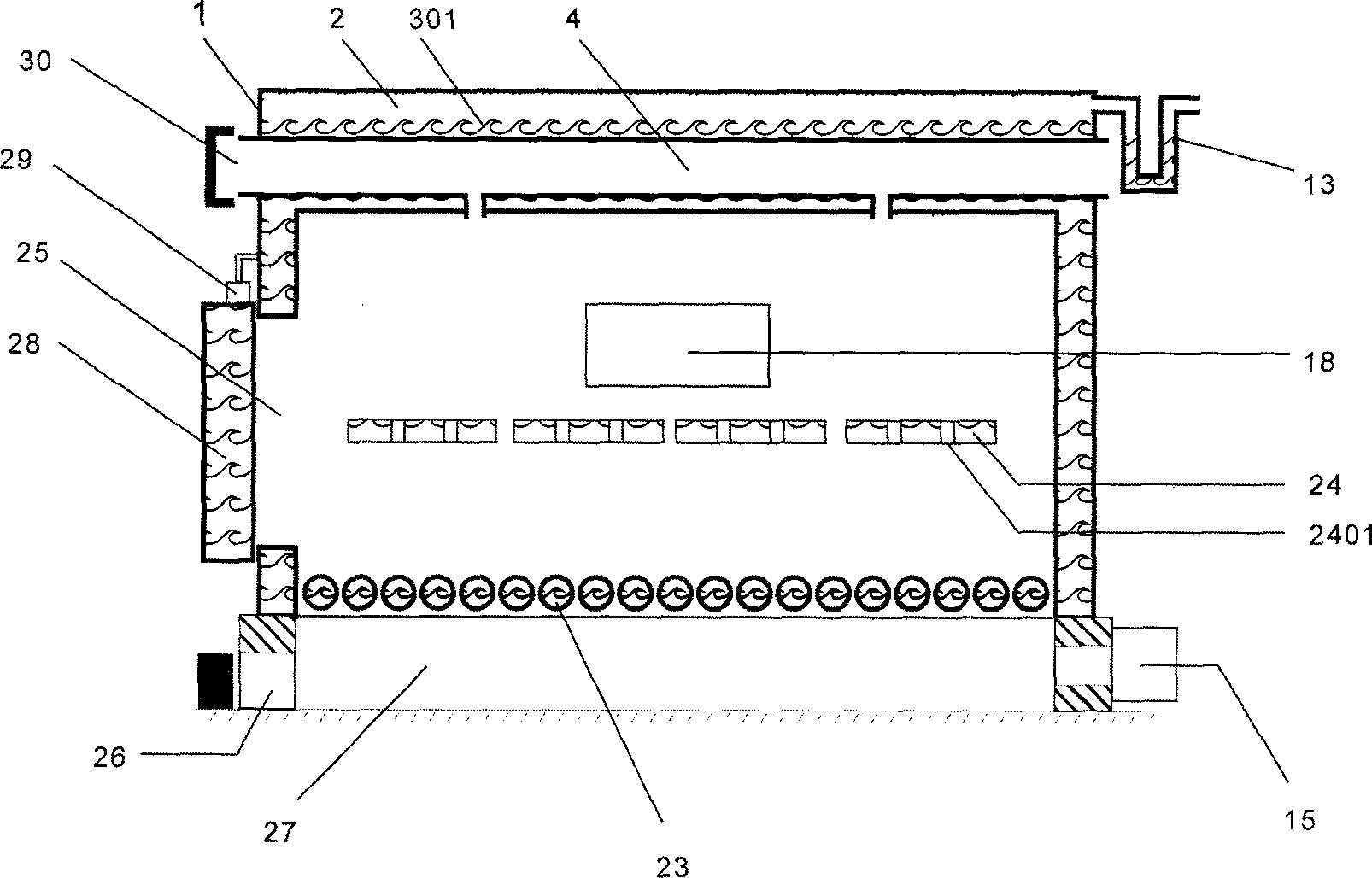
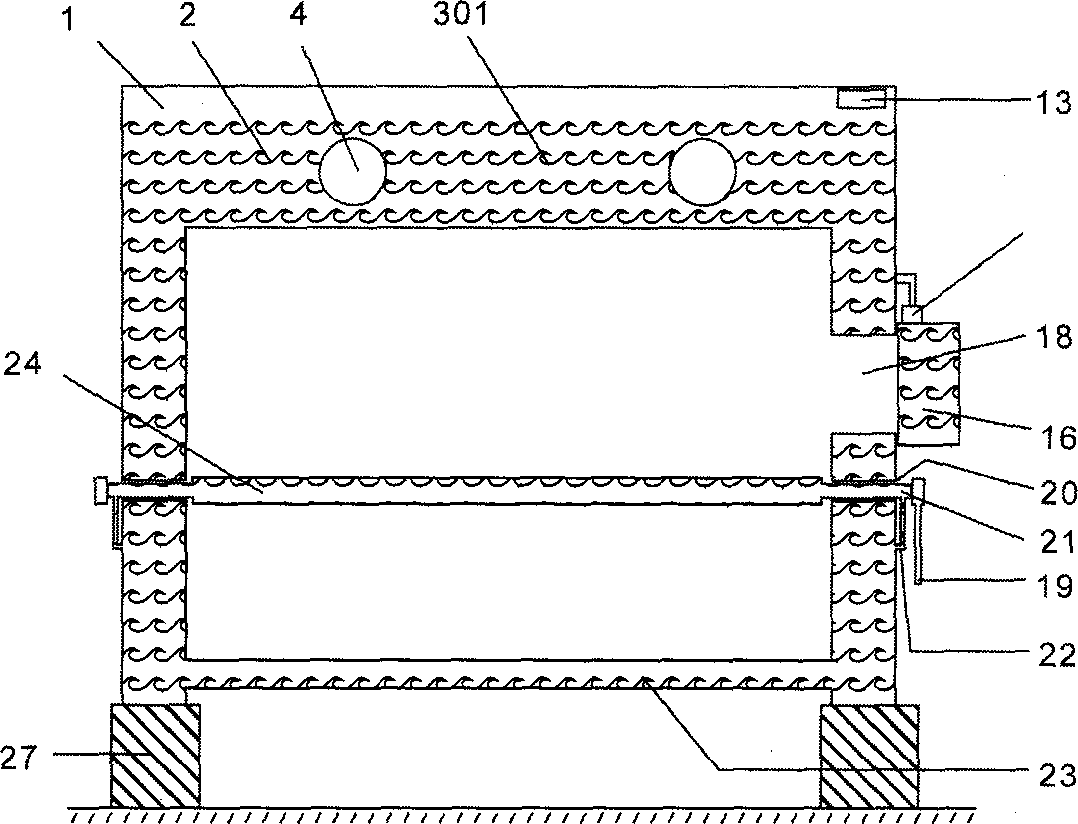
[0059] Because the drawings involved in the present invention involve large-scale devices and small components, the small components are enlarged in the composition to facilitate their description. Therefore, the relative sizes of the components in the composition are not in actual proportion, and should not be understood as Scale constraints on relative sizes.
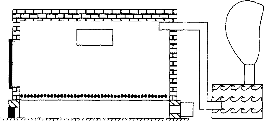
[0060] Such as figure 1 In the existing small incinerator shown, the four walls of the existing furnace body are solid structures, and the middle is a combustion chamber. Usually, refractory bricks are used as building materials. A row of incineration grates is laid on the bottom of the furnace body to support the burning waste The distance between the support tubes is 2-5CM for ventilation and combustion, and the combustion residue can fall into the furnace base below. The existing incineration grate is a solid material; the furnace base below the furnace is the furnace base. The load-bearing base of the furnace bod...
PUM
 Abstract
Description
Claims
Application Information