
Method for forming semiconductor device

A semiconductor and device technology, applied in the field of semiconductor device formation, can solve the problems of expensive, time-consuming, repeated exposure steps, etc., and achieve the effect of reducing process difficulty and production cost, and reducing cost

Active Publication Date: 2017-06-16
SEMICON MFG INT (SHANGHAI) CORP
View PDF3 Cites 0 Cited by
  • Summary
  • Abstract
  • Description
  • Claims
  • Application Information

AI Technical Summary

Problems solved by technology

The full LELE process is time consuming and expensive
Time consuming because the first exposed wafer needs to be etched once before the second exposure
Expensive due to repeated exposure steps

Method used


Image

  • Method for forming semiconductor device
  • Method for forming semiconductor device
  • Method for forming semiconductor device

Examples


no. 1 example

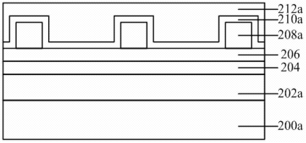
[0039] refer to figure 1 , providing a semiconductor substrate 200a, and forming a first mask layer on the semiconductor substrate 200a.

[0040] In this embodiment, the material of the semiconductor substrate 200a can be single crystal silicon, single crystal germanium or single crystal silicon germanium, silicon-on-insulator, III-V group element compounds, single crystal silicon carbide, etc. other materials.

[0041] In addition, a device structure (not shown in the figure) may also be formed in the semiconductor substrate 200a, and the device structure may be a device structure formed in a semiconductor front-end process, such as a MOS transistor.

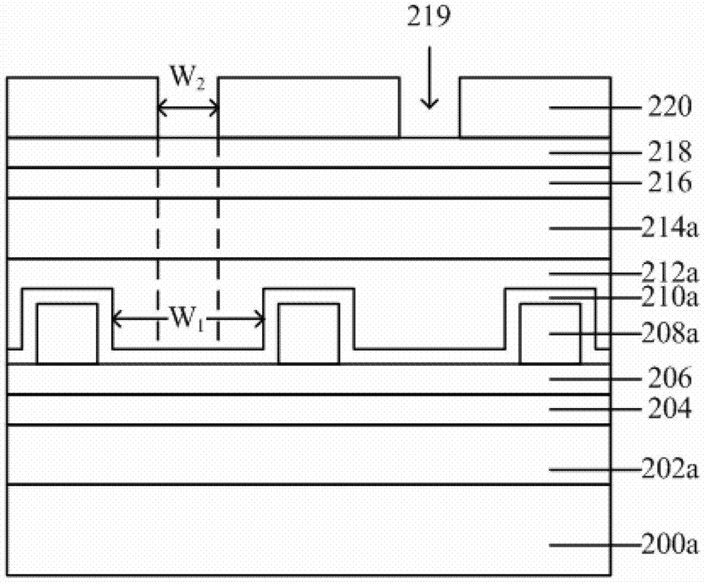
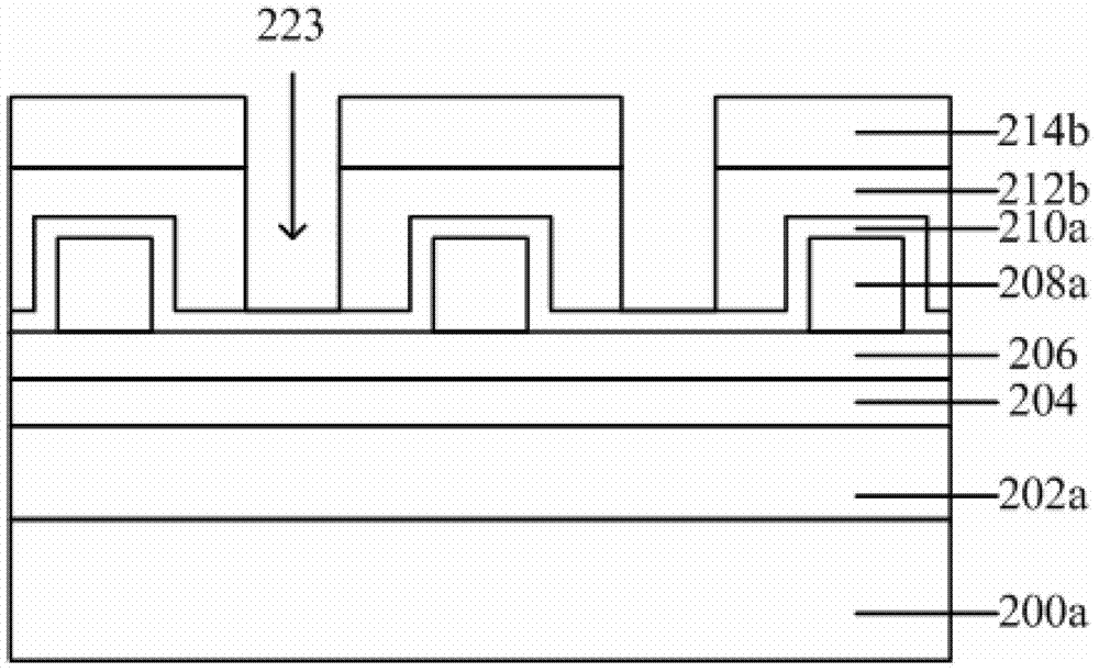
[0042] In this embodiment, the first mask layer is a multi-layer structure, and forming the first mask layer on the semiconductor substrate 200a includes: sequentially forming an organic distribution layer 202a, a second mask layer on the semiconductor substrate 200a from bottom to top, Two hard mask layers 204, bottom anti-...

no. 2 example

[0081] refer to Figure 8 , providing a semiconductor substrate 300a, and forming a first mask layer on the semiconductor substrate 300a.

[0082] In this embodiment, the first mask layer is a multi-layer structure, and forming the first mask layer on the semiconductor substrate 300a includes: sequentially forming an organic distribution layer 302 on the semiconductor substrate 300a from bottom to top , a second hard mask layer 304 and a photoresist layer.

[0083] In this embodiment, please refer to the first embodiment for the structure and formation process of the semiconductor substrate 300 a , the organic distribution layer 302 , the second hard mask layer 304 and the photoresist layer, and details are not repeated here.

[0084] In another embodiment, after forming the second hard mask layer 304 and before forming the photoresist layer, forming a bottom anti-reflection layer on the second hard mask layer 304 may also be included. (not shown).

[0085] continue to refe...


PUM


Abstract

A semiconductor device forming method includes providing a semiconductor substrate, forming a first mask layer on the semiconductor substrate, forming a first groove penetrating the first mask layer for a part of thickness, filling the first groove with a first hard mask layer, forming a second groove penetrating the first hard mask layer for the thickness of the first hard mask layer; utilizing the first hard mask layer as a mask to etch the first mask layer and the semiconductor substrate till a through hole or a groove is formed in the semiconductor substrate. By means of the semiconductor device forming method, only one etching process is required in formation of the through hole or the groove through a double graph technology, double graph forming process difficulty and manufacture cost are reduced, and the semiconductor device forming cost is further reduced.

Description

technical field [0001] The invention relates to the technical field of semiconductor manufacturing, in particular to a method for forming a semiconductor device. Background technique [0002] In order to integrate more and smaller transistors on a chip, new photolithography techniques must be developed to continuously reduce the size of transistors. [0003] One direction of development in lithography is to fundamentally shorten the wavelength of light used in optical lithography. The current lithography technology is committed to the development of extreme ultraviolet (EUV) lithography technology with a wavelength of 13.5nm. Using EUV lithography technology may result in chips with feature sizes smaller than 32nm. Chips using EUV lithography will end up being 100 times faster and have 100 times more storage than even the most processing-capable chips available today. However, there are still many problems in the current EUV lithography technology that have not been resol...

Claims


Application Information

Patent Timeline
Patent Type & Authority Patents(China)
IPC IPC(8): H01L21/02H01L21/027H01L21/768
CPCH01L21/0338H01L21/76898
Inventor 王冬江张海洋
Owner SEMICON MFG INT (SHANGHAI) CORP
Learn More