Adjustable underground alternate-irrigation device
A technology of alternate irrigation and sprinklers, applied in watering devices, gardening, botanical equipment and methods, etc., can solve the problems of low irrigation water utilization efficiency, buried in the ground, difficult location, etc., and achieve high water use efficiency and utilization Effects of improving efficiency and suppressing evaporation loss
- Summary
- Abstract
- Description
- Claims
- Application Information
AI Technical Summary
Problems solved by technology
Method used
Image
Examples
Embodiment 1
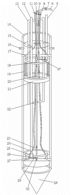
[0057] Embodiment 1: as figure 1 As shown in -22, the adjustable underground alternate irrigation device of the present invention includes a cylinder 14, a soil-breaking cone 28, an irrigation mechanism, a water supply pipe fitting, an irrigation operation mechanism, and an irrigation direction operation mechanism. Installed in the cylinder body 14, the water supply pipe is connected with the irrigation mechanism, and the irrigation operation mechanism and the irrigation direction operation mechanism are connected with the irrigation mechanism;
[0058] The irrigation mechanism includes an upper irrigation mechanism and a lower irrigation mechanism, wherein the upper irrigation mechanism includes an upper anti-clogging cylinder 15, an upper sprinkler 17, a cylindrical spring 19, a cylindrical spring seat 21, and the cylindrical spring seat 21 is fixed on the cylinder 14 top, The cylindrical spring 19 is installed on the cylindrical spring seat 21, the bottom of the upper anti-...
Embodiment 2
[0073] Embodiment 2: The structure of the device in this embodiment is the same as in Embodiment 1. After adjusting the vertical distance between the upper emitter 17 and the lower emitter 27 by using the method of Embodiment 1, press down on the upper emitter direction control lever 5, and the direction of the upper emitter The operating rod 5 can drive the upper emitter connecting rod 18 to move to the left, and the upper emitter connecting rod 18 is connected with the upper inner threaded pipe 58 by a pin, and the upper emitter connecting rod 18 can drive the upper emitter 17 to move in the horizontal plane, and the lower The emitter direction operating lever 12 does not perform pulling and pressing operations, and continues to press down the upper emitter direction operating lever 5, and at the same time pulls up the emitter operating lever 13 until the upper emitter 17 passes through the upper emitter on the upper anti-blocking cylinder 15 The upper emitter access hole I62...
Embodiment 3
[0074] Embodiment 3: The device structure of this embodiment is the same as that of Embodiment 1. After adjusting the vertical distance between the upper emitter 17 and the lower emitter 27 using the method of Embodiment 1, pull up and down the emitter direction control lever 12, and the direction of the lower emitter The operating rod 12 will drive the lower emitter 27 to move in the horizontal plane. The operating rod 5 in the direction of the upper emitter will not be pulled or pressed, and the operating rod 12 in the direction of the upper emitter will continue to be pulled up, and the operating rod 13 will be pressed down at the same time until The lower emitter 27 protrudes through the lower emitter access channel 55 on the lower anti-blocking cylinder 24 and the lower emitter access hole I63 or the lower emitter access hole II66 on the cylinder body 14, and opens the main water valve 7 and the water diversion valve Ⅲ10, realizing the function of water irrigation by the l...
PUM
 Abstract
Description
Claims
Application Information
 - R&D
- Intellectual Property
- Life Sciences
- Materials
- Tech Scout
- Unparalleled Data Quality
- Higher Quality Content
- 60% Fewer Hallucinations
Browse by: Latest US Patents, China's latest patents, Technical Efficacy Thesaurus, Application Domain, Technology Topic, Popular Technical Reports.
© 2025 PatSnap. All rights reserved.Legal|Privacy policy|Modern Slavery Act Transparency Statement|Sitemap|About US| Contact US: help@patsnap.com


