
Multi-stage cone cavity fixed hammer crusher

A conical cavity and crusher technology, applied in grain processing, etc., can solve the problems of lack of crushing equipment, achieve high crushing efficiency, large crushing force, and improve the effect of crushing

Active Publication Date: 2017-02-01
TONGJI UNIV
View PDF5 Cites 0 Cited by
  • Summary
  • Abstract
  • Description
  • Claims
  • Application Information

AI Technical Summary

Problems solved by technology

Large pieces of FRP waste such as wind turbine blades can be cut into 500mm-1000mm with a diamond wire cutting machine, and then cut into 80mm-250mm with a single-shaft crusher. Lack of effective crushing equipment

Method used


Image

  • Multi-stage cone cavity fixed hammer crusher
  • Multi-stage cone cavity fixed hammer crusher
  • Multi-stage cone cavity fixed hammer crusher

Examples


Embodiment 1

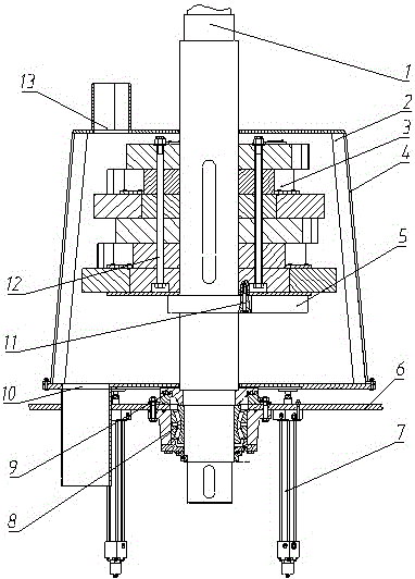
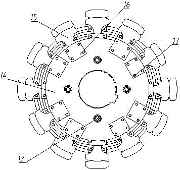
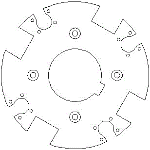
[0018] Embodiment 1: As shown in the figure, a conical shell 4 is equipped with a liner 2 to form a conical crushing chamber, and the main shaft 1 in the crushing chamber is fixed on the frame 6 through a bearing 8 and a bearing sealing and lubricating device 9 . The main shaft 1 is equipped with six layers of cutterhead hammerhead assemblies 3 stacked and fixed with long studs 12. The nominal diameter of each layer of cutterhead hammerhead assemblies 3 increases sequentially from top to bottom, and the gap between them and the crushing cavity wall then decrease in turn. There are round grooves and square grooves alternately formed on the circular edge of the cutter head assembly 3. Starting from the first layer, taking the central axis of the square groove as the reference, the cutter heads of each layer are shifted by 30 degrees in turn, and the round grooves There are four bolt holes around it, facing the lower square groove. One end of the hammer head 15 is fixed in the ci...


PUM


Abstract

The invention relates to a multistage conical cavity fixed hammerhead crusher. Multiple layers of cutterheads are arranged on the main shaft of the conical crushing cavity from the top to bottom in a tower shape. Each layer of cutterhead is fixedly provided with a plurality of hammerheads. A substance, which enters the crushing cavity from the top of the crushing cavity, is punched by the hammerheads arranged on the cutterheads that rotate in a high speed and are perpendicular to the main shaft, and extruded and grinded by the hammerheads and cavity wall into powder. The hammerheads on the cutterhead are staggeredly arranged, so that a plurality of hammerheads can be arranged in the same descending path so as to increase the punching frequency on the substance. The space between the hammerheads and the cavity wall becomes narrower from the top to the bottom and can be changed by changing the height of the machine. The substance is grinded in each stage during the descending process, and is finally discharged out of the crusher when the particle size of the substance is equal to the distance between the hammerhead in the lowest stage and the cavity wall.

Description

technical field [0001] The invention belongs to the technical field of crushing machinery, and in particular relates to a multi-stage cone cavity fixed hammerhead crusher. Background technique [0002] With the rapid increase in the production and use of FRP in my country year by year, the waste of FRP is increasing. Due to the excellent corrosion resistance of FRP, it is difficult to destroy it naturally. The threat of FRP waste to the environment is increasing, and the demand for the disposal of these wastes is becoming more and more urgent. At present, the more economical and environmentally friendly treatment method is to treat them Recycling after physical pulverization or chemical pyrolysis is used as filler for reuse. Both methods require crushing of waste with different particle sizes. Large pieces of FRP waste such as wind turbine blades can be cut into a size of 500mm-1000mm with a diamond wire cutting machine, and then cut into 80mm-250mm with a single-shaft crus...

Claims


Application Information

Patent Timeline
Patent Type & Authority Patents(China)
IPC IPC(8): B02C21/00
Inventor 陈茂林李梦如卜王辉张攀奚鹰
Owner TONGJI UNIV
Learn More