
Universal automatic machining device for turning and milling of screwdriver head

A technology of automatic processing and screwdriver bits, which is applied in the direction of manufacturing tools and other manufacturing equipment/tools, etc., can solve the problems of single processing object and process, high cost of screwdriver head processing, unsuitable screwdriver bits, etc., to simplify the assembly structure and improve The effect of reciprocating feed speed and work efficiency, and convenient equipment maintenance

Inactive Publication Date: 2014-11-05
刘勉生
View PDF9 Cites 10 Cited by
  • Summary
  • Abstract
  • Description
  • Claims
  • Application Information

AI Technical Summary

Problems solved by technology

[0005] In order to overcome the single processing object and process of the existing screwdriver head turn-milling compound machine, which is not suitable for processing most of the screwdriver bits at present, and the existing general-purpose turn-milling compound machining center has too high processing cost for processing screwdriver bits, However, the working efficiency is not high, and the processing difficulty of certain procedures is large. The purpose of the present invention is to provide an improved universal turning and milling compound automatic processing device for screwdrivers, which can overcome the defects of the prior art.

Method used


Image

  • Universal automatic machining device for turning and milling of screwdriver head
  • Universal automatic machining device for turning and milling of screwdriver head
  • Universal automatic machining device for turning and milling of screwdriver head

Examples


Embodiment Construction

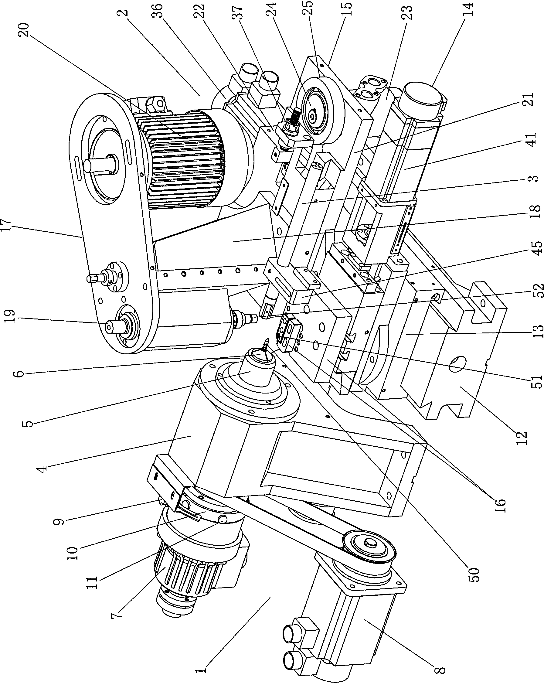
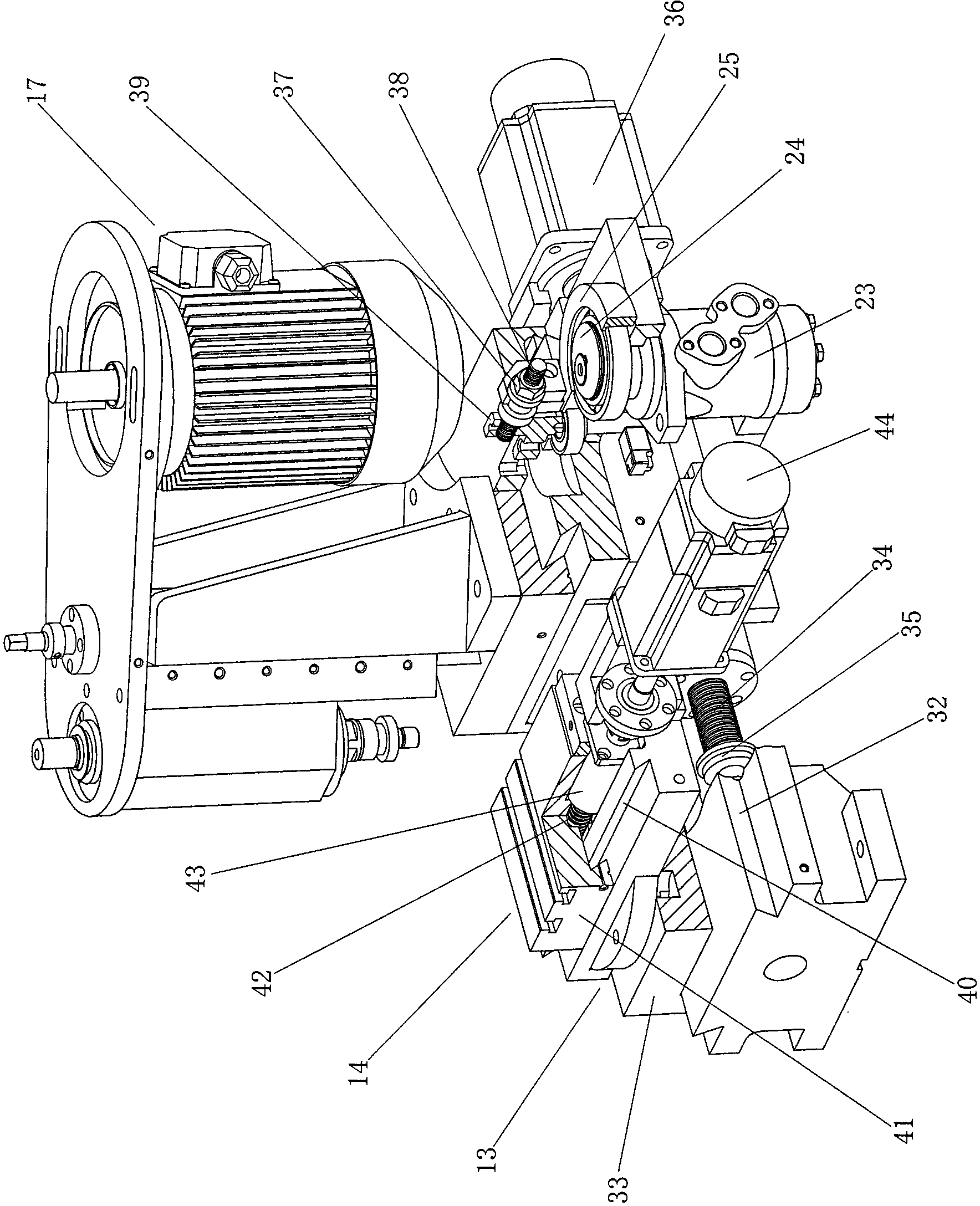
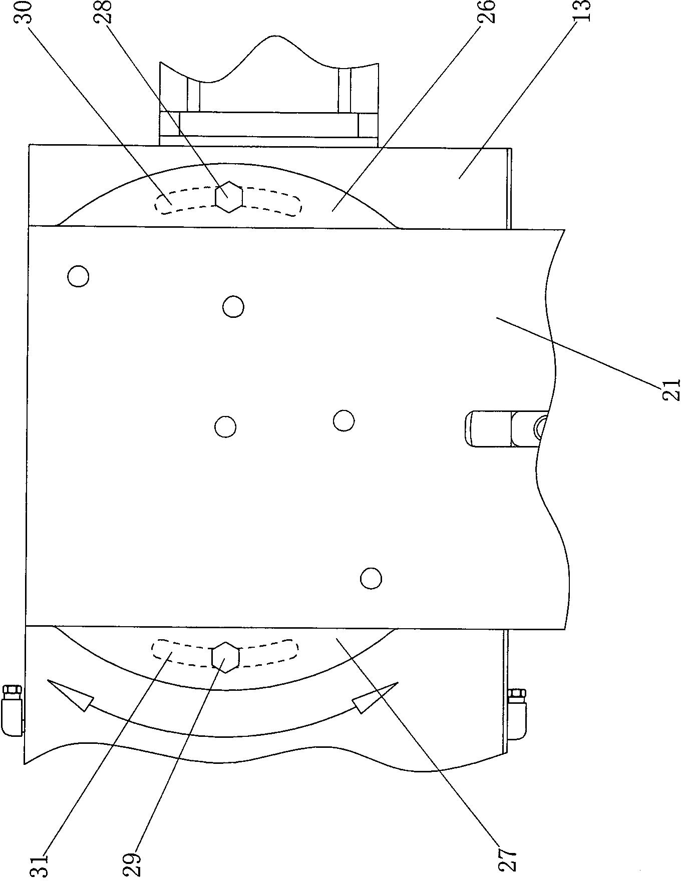
[0021] refer to figure 1 , the universal turning and milling compound automatic processing device for the screwdriver head is characterized in that it includes a clamping fixed-point rotating assembly 1 installed on the machine base, a turning and milling tool compound feeding assembly 2 and a workpiece conveyor 3, wherein the clamping The fixed-point rotating assembly 1 is composed of an assembly seat 4, a hollow main shaft 5 that rotates and fits on the assembly seat 4, a sliding openable collet 6 that fits in the shaft cavity of the hollow main shaft 5 and exposes the front end of the hollow main shaft 5, and is installed and fixed on the assembly The hollow rotary hydraulic cylinder 7 on the base 4 and matched with the sliding collet 6, the servo motor 8 installed on the machine base and drivingly connected with the hollow main shaft 5, and the circumferential fixed-point sensor installed on the assembly base 4 9 and several circumferential fixed-point sensing blocks 11 ar...


PUM


Abstract

The invention discloses a universal automatic machining device for turning and milling of a screwdriver head. The universal automatic machining device for turning and milling of the screwdriver head aims to overcome the defects that according to existing similar machining devices, the machining objects and the machining process are not diversified, and the existing similar machining devices are not suitable for machining of most existing screwdriver heads; according to an existing universal machining center for turning and milling, the machining cost of the screwdriver heads is excessively high and the working efficiency is low. According to the technical scheme, the universal automatic machining device for turning and milling of the screwdriver head is characterized by comprising a clamping and fixed-point rotating assembly, a turning and milling tool composite feeding assembly and a workpiece conveying device, the clamping and fixed-point rotating assembly is composed of an assembly base, a hollow main shaft, a sliding openable chuck, a hollow rotating oil hydraulic cylinder, a servo motor, a circumferential fixed-point inductor and a circumferential fixed-point induction block, the turning and milling tool composite feeding assembly is composed of an assembly table, a transversely-feeding mechanism, a turning longitudinally-feeding mechanism, a milling longitudinally-feeding mechanism, a turning tool rest and a milling device, the milling device is composed of a base body, a vertically-milling main shaft and a milling motor, and the milling longitudinally-feeding mechanism is composed of a sliding rail plate, a sliding base, an oil motor, an eccentric wheel and an eccentric wheel rim.

Description

technical field [0001] The invention relates to processing equipment for hardware tools, in particular to a universal turning-milling compound automatic processing device for screwdriver heads. Background technique [0002] A screwdriver is a hand tool for tightening or loosening screws, also known as a screwdriver, screwdriver, etc. A screwdriver is generally composed of a screwdriver handle and a screwdriver shaft combined together. The screwdriver head on the screwdriver shaft is called a screwdriver head. The screwdriver head can be integrated with the screwdriver shaft or can be an independent component. Screwdriver bits generally need to go through multiple processes of turning and milling to complete the processing, and the current special processing equipment for screwdriver bits are independent special-purpose lathes and independent special-purpose milling machines. Positioning, resulting in low processing accuracy and processing efficiency, high processing costs....

Claims


Application Information

Patent Timeline
Patent Type & Authority Applications(China)
IPC IPC(8): B23P23/02
CPCB23P23/02
Inventor 刘勉生
Owner 刘勉生
Learn More