A flash dryer

A flash dryer and drying cylinder technology, used in dryers, drying solid materials, drying gas layout, etc., can solve the problems of large airflow resistance, filter cake-like and paste-like materials, etc., and achieve airflow resistance. Small, shortened drying time, significant energy saving effect

Inactive Publication Date: 2016-10-05
SOUTH CHINA UNIV OF TECH
View PDF7 Cites 0 Cited by
  • Summary
  • Abstract
  • Description
  • Claims
  • Application Information

AI Technical Summary

Problems solved by technology

[0004] The purpose of the present invention is to overcome the shortcomings and deficiencies of the above-mentioned prior art, and provide a flash dryer, which can effectively solve the problem of breaking up filter cake and paste materials, effectively solve the problem of large airflow resistance, and achieve the purpose of energy saving

Method used


Image

  • A flash dryer

Examples


Embodiment

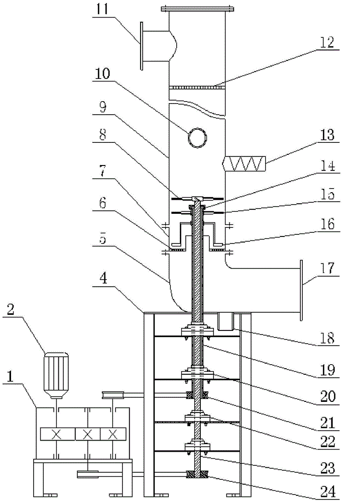
[0029] like figure 1 shown. The flash dryer of the present invention includes a transmission mechanism and a material breaking mechanism, and the material breaking mechanism includes a hollow outer rotating shaft 19 and an inner rotating shaft 23 arranged in the hollow outer rotating shaft 19; it also includes a drying cylinder 9 sequentially connected from top to bottom , sieve plate section tube 7, air inlet tube 5; the transmission mechanism includes an inner shaft drive mechanism and a hollow outer shaft drive mechanism;

[0030] The lower section of the drying cylinder 9 is equipped with an upper blade 8 and a lower blade 15 for breaking up materials;

[0031] The upper blade 8 is connected to the inner shaft 23, and the inner shaft 23 is connected to the inner shaft driving mechanism through the inner shaft pulley 24; the lower blade 15 is connected to the hollow outer shaft 19, and the hollow outer shaft 19 is connected to the hollow outer shaft driving mechanism throu...


PUM


Abstract

The invention discloses a flash drying machine, which comprises a transmission mechanism and a material breaking-up mechanism. The material breaking-up mechanism includes a hollow outer rotating shaft and an inner rotating shaft arranged inside the hollow outer rotating shaft; it also includes drying cylinders sequentially connected from top to bottom , sieve plate section cylinder, and air inlet cylinder; the transmission mechanism includes an inner shaft drive mechanism and a hollow outer shaft drive mechanism; the lower section of the drying cylinder is equipped with an upper blade and a lower blade for breaking up materials; the upper blade is connected to the inner shaft, and the inner The rotating shaft is connected with the inner rotating shaft driving mechanism through the inner rotating shaft pulley; the lower blade is connected with the hollow outer rotating shaft, and the hollow outer rotating shaft is connected with the hollow outer rotating shaft driving mechanism through the hollow outer rotating shaft pulley. The combined shaft system of the hollow outer shaft and the inner shaft realizes the opposite high-speed rotation of the upper and lower blades, which can make the lumpy or pasty materials reciprocate and hit between the upper and lower blades at a high speed, and has the ability to disperse more thoroughly. , the wet material particles are finer, and the energy saving effect is remarkable.

Description

technical field [0001] The invention relates to airflow drying equipment and energy saving thereof, in particular to a flash drying machine. Background technique [0002] Flash dryer is a large-scale drying equipment integrating drying technology and fluidization technology. Compared with other drying equipment, it has the advantages of continuous operation, compact structure, convenient operation, less failure and low maintenance cost. Existing flash dryers generally include a flash drying chamber, a dispersing device, a transmission device, an air inlet, a feed inlet, a classifier, and a discharge outlet. The hot air enters the drying chamber from the annular gap at the bottom of the drying cylinder. The materials are broken up by the dispersing device and fully contact with the hot air to complete the heat transfer and mass transfer process. The hot air carrying the materials leaves the drying chamber after being filtered by the classifier and enters the bag Separation e...

Claims


Application Information

Patent Timeline
Patent Type & Authority Patents(China)
IPC IPC(8): F26B17/10F26B21/00F26B25/04
Inventor 冯毅刘颂
Owner SOUTH CHINA UNIV OF TECH
Why Eureka
Try Eureka