Minimally-invasive transection device for pediculus arcus vertebrae

A pedicle and severing technology, which is used in medical science, surgical sawing, surgery, etc., can solve the problems of great harm, large axial jumping and radial shaking of cutting tools, and no guarantees, so as to reduce the need for surgery. The effect of risk, high adjustment accuracy and convenient operation

Active Publication Date: 2014-11-12
SOUTHERN MEDICAL UNIVERSITY
View PDF5 Cites 1 Cited by
  • Summary
  • Abstract
  • Description
  • Claims
  • Application Information

AI Technical Summary

Problems solved by technology

It is not difficult to see that the above-mentioned patent application still has the following defects: when the cutting rod 2 is driven to and fro by the handle 6, there is no point of force to ensure its stability on the entire cutting tool, and it can only be supported by an assistant in the most ideal situation. The sleeve rod 1, so the whole cutting tool inevitably has a large range of axial vibration and radial vibration
Wherein, the said axial je

Method used


Image

  • Minimally-invasive transection device for pediculus arcus vertebrae
  • Minimally-invasive transection device for pediculus arcus vertebrae
  • Minimally-invasive transection device for pediculus arcus vertebrae

Examples


Example Embodiment

[0026] Example 1:

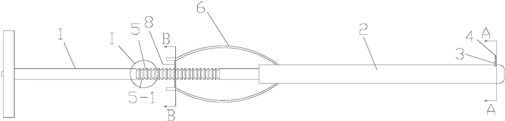
[0027] Such as figure 1 , figure 2 with image 3 The shown minimally invasive pedicle severing device includes a saw core 1, a saw sheath 2, and a feeding mechanism,

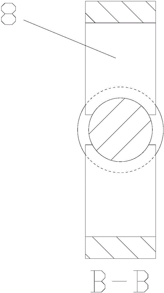
[0028] The saw sheath 2 is in the shape of a round rod, and a circular hole is arranged axially in the body. The circular hole is radially contracted into a flat hole with a rectangular cross section on the two opposite sides close to the distal end of the saw sheath 2. The side wall of φ is bent and extends through the outer wall of the saw sheath 2;

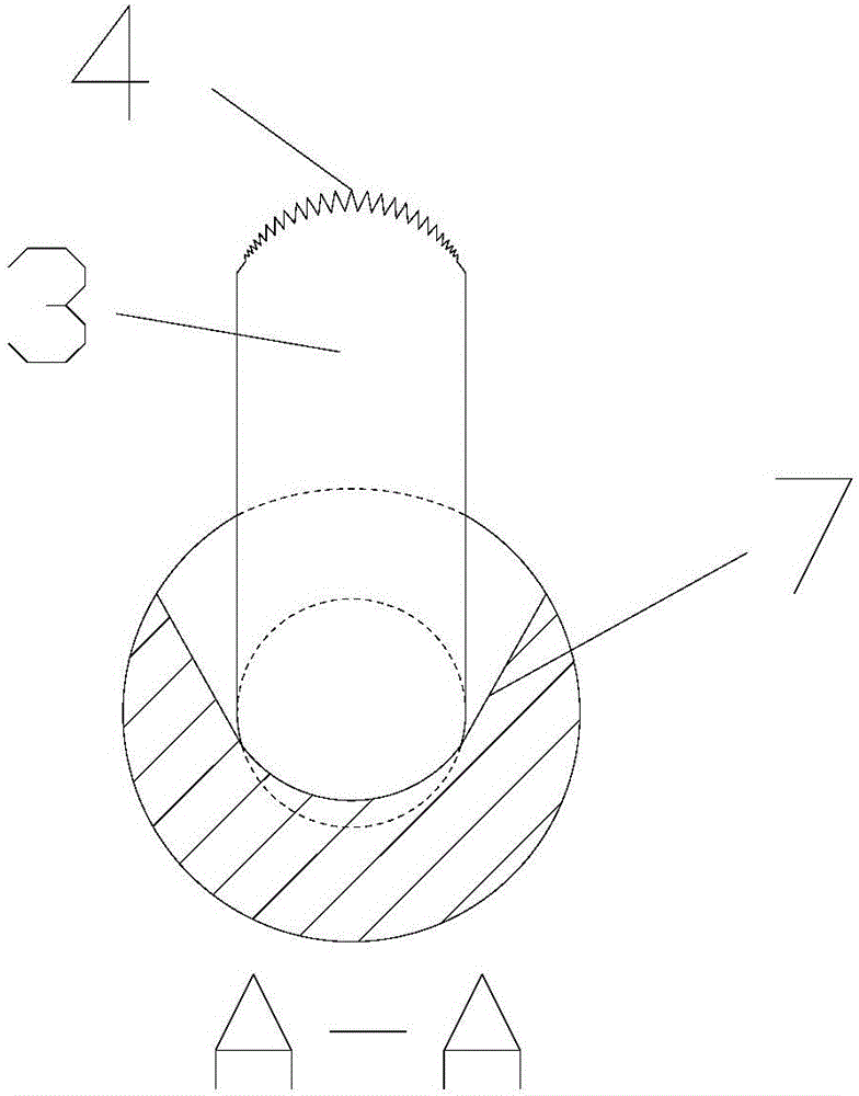
[0029] The saw core 1 is in the shape of a round rod that matches the round hole provided in the saw sheath 2, and it penetrates the round hole in the saw sheath 2, and the proximal end extends beyond the proximal end of the saw sheath 2, and the diameter of the two opposite sides of the distal end Shrink to form a flat structure 3 with a rectangular cross section, the flat structure 3 matches the flat hole provided at the distal end of the saw s...

Example Embodiment

[0038] Example 2:

[0039] Such as Figure 5 The structure of another minimally invasive pedicle severing device shown is the same as that of Embodiment 1 except for the following description: it also includes a fixing frame 9 which is rod-shaped and has a mounting hole transversely in the middle. The proximal end of the sheath 2 is inserted and fixed in the mounting hole; the distal ends of the two elastic arms 6 are fixedly connected with the saw sheath 2 via a fixing frame, and the middle part of each elastic arm 6 is bent radially toward each other. The function of the fixing frame 9 is to make it easier to grip the saw sheath 2 or to fix the saw sheath 2. The use process of the minimally invasive pedicle severing device of Example 2 is basically the same as that of Example 1.


PUM


Abstract

The invention discloses a minimally-invasive transection device for pediculus arcus vertebrae. The minimally-invasive transection device comprises a saw core, a saw sheath and a feeding mechanism, wherein the saw sheath is circular-rod-shaped, a circular hole is axially formed in a saw sheath body, two opposite faces, close to a distant end location of the saw sheath, of the circular hole are subjected to radial contraction, so as to form a flat hole, of which the cross section is rectangular, and the flat hole bends towards the sidewall of the saw sheath and extends out of the external wall of the saw sheath; two side faces, in the width direction of the flat holes, of the distant end of the saw sheath are obliquely expanded from inside to outside, so as to provide a space for rotating back and forth around the central axis of the saw core when a flat structure of the distant end of the saw core extends out of the flat hole. According to the minimally-invasive transection device, during use, the saw core rotates, the saw sheath is stationary, and both the saw core and the saw sheath cannot be subjected to axial movement, so that the axial locating is accurate and does not shift, and the surgery is completed safely and efficiently.

Description

Technical field [0001] The invention relates to a medical surgical instrument, in particular to a surgical cutting instrument. Background technique [0002] Lumbar spinal stenosis refers to a series of spinal canal or nerve root canal or intervertebral foramen stenosis caused by various reasons such as intervertebral disc protrusion, bone hyperplasia or fibrous tissue hyperplasia, hypertrophy, and stimulation and compression of nerve roots or cauda equina Clinical symptoms. [0003] Clinically, surgical methods are currently used for treatment. The traditional open compression surgery has gradually given way to minimally invasive surgery due to the disadvantages of large trauma, high blood loss, susceptibility to infection, and slow postoperative recovery. Minimally invasive surgery is an inevitable trend in the development of surgery. Minimally invasive treatments for lumbar spinal stenosis include percutaneous screw and rod system placement, spinous process distraction, and pedi...

Claims


Application Information

Patent Timeline
IPC IPC(8): A61B17/14A61B17/56
CPCA61B17/142A61B2017/00261A61B2017/564
Inventor 房亚峰欧阳钧孙培栋
Owner SOUTHERN MEDICAL UNIVERSITY
Why Eureka
Try Eureka