Redox flow cell system

A flow battery and stack technology, applied in indirect fuel cells, fuel cell components, etc., can solve the problems of cumbersome, power consumption and manpower, so as to improve the utilization rate, reduce maintenance costs, and avoid power and manpower. Effect

Inactive Publication Date: 2014-11-12
DALIAN INST OF CHEM PHYSICS CHINESE ACAD OF SCI
View PDF2 Cites 5 Cited by
  • Summary
  • Abstract
  • Description
  • Claims
  • Application Information

AI Technical Summary

Problems solved by technology

This process is not only cumbersome, but also consumes extra power and manpower

Method used


Image

  • Redox flow cell system
  • Redox flow cell system
  • Redox flow cell system

Examples


Embodiment 1

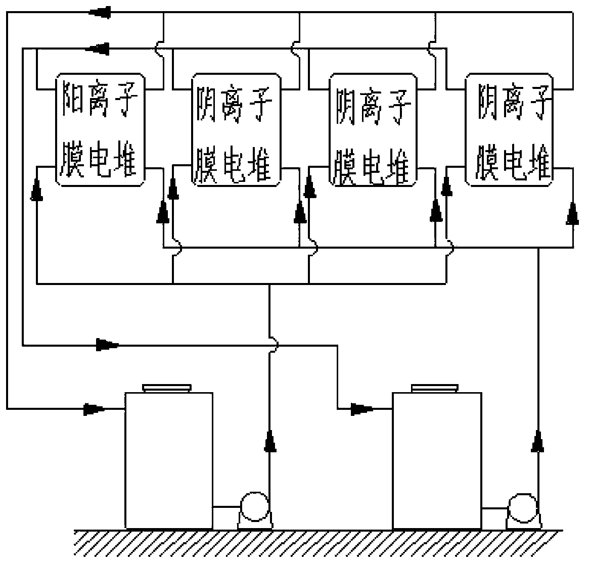
[0029] The measured all-vanadium redox flow battery system is composed of 4 stacks, and the ratio of the number of cationic membrane stacks and anion membrane stacks that make up the all-vanadium redox flow battery system is 1 / 3, and each stack The number of single cells is 5, and the arrangement of the cation membrane stacks and anion membrane stacks used to form the all-vanadium redox flow battery system is not limited. In this embodiment, the composition of the all-vanadium redox flow battery system The arrangement of cation membrane stack and anion membrane stack is as follows figure 1 shown. The system is composed of 4 stacks, the ratio of the number of cation membrane stacks and anion membrane stacks that make up the all-vanadium redox flow battery system is 1 / 3, and the cations that make up the all-vanadium redox flow battery system Membranes and anion membranes can be arranged in any way, and this picture is just one of them.

Embodiment 2

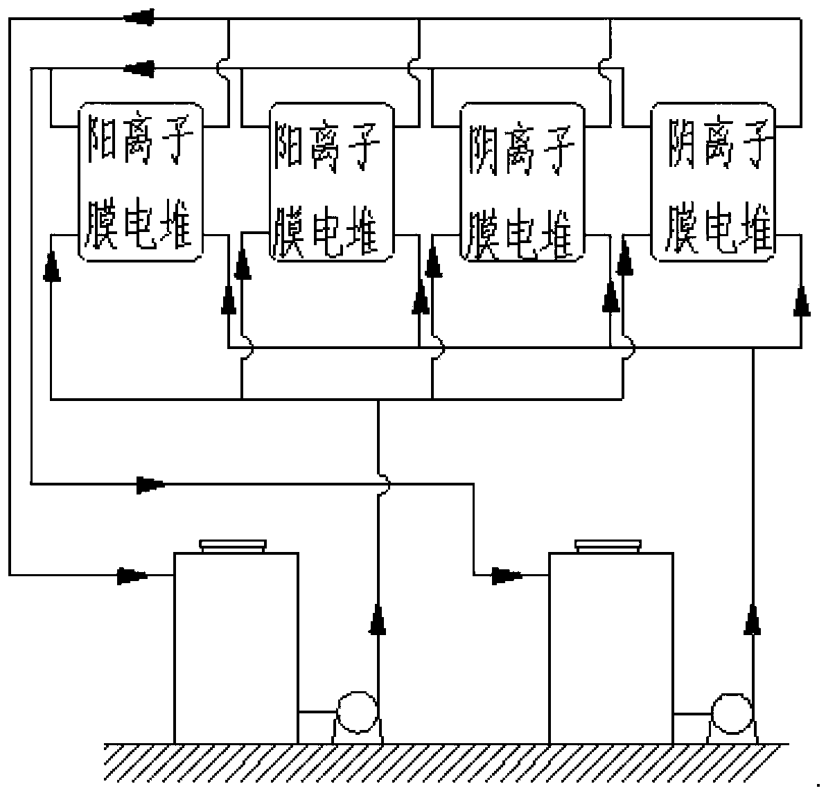
[0031] The tested all-vanadium redox flow battery system is composed of 4 stacks, and the ratio of the number of cationic membrane stacks and anion membrane stacks that make up the all-vanadium redox flow battery system is 2 / 2, and each stack The number of single cells is 5, and the arrangement of the cation membrane stacks and anion membrane stacks used to form the all-vanadium redox flow battery system is not limited. In this embodiment, the composition of the all-vanadium redox flow battery system The arrangement of cation membrane stack and anion membrane stack is as follows figure 2 shown.

Embodiment 3

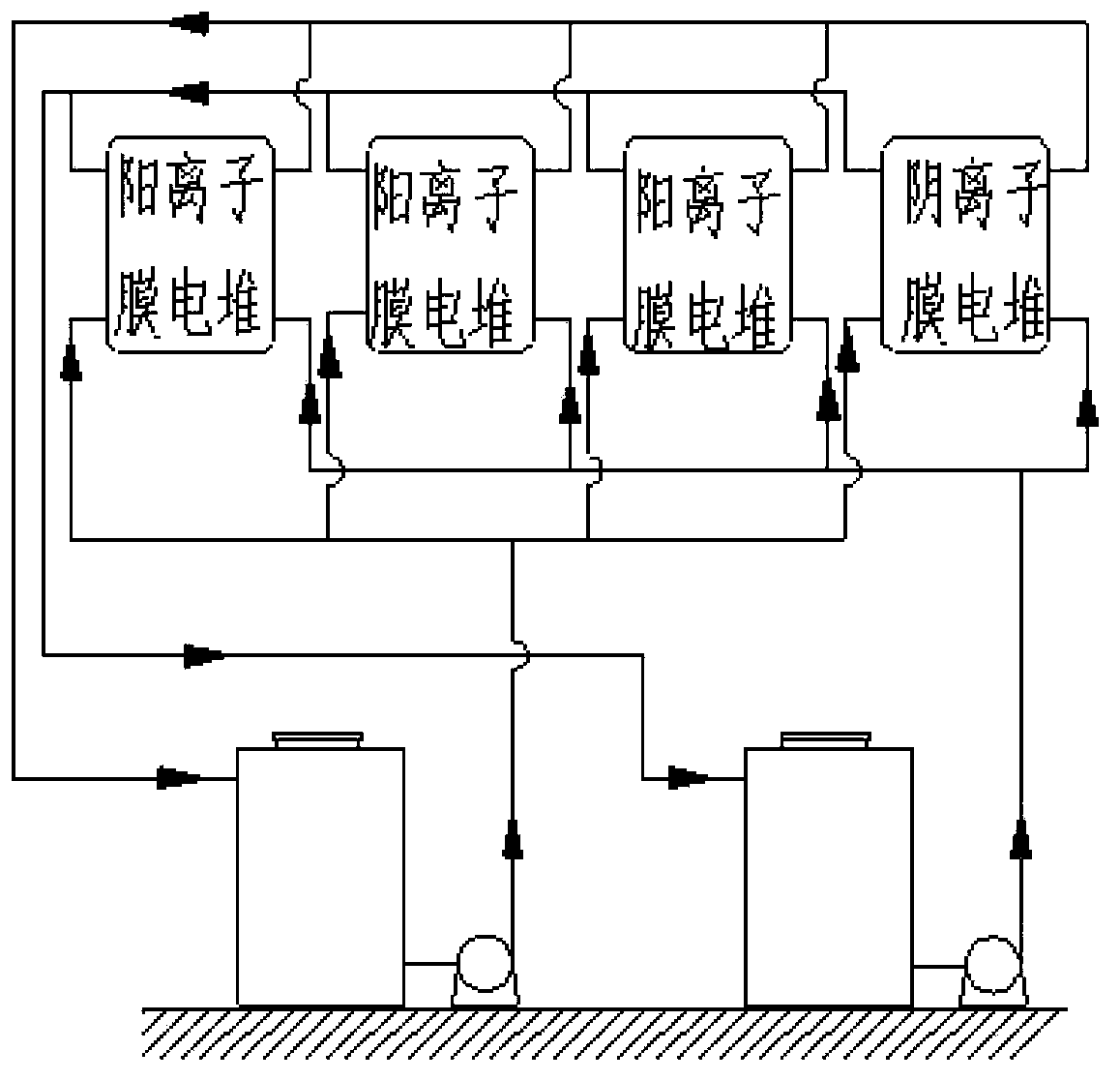
[0033] The tested all-vanadium redox flow battery system is composed of 4 stacks, in which the ratio of the number of cationic membrane stacks and anion membrane stacks that make up the all-vanadium redox flow battery system is 3 / 1, and each stack The number of single cells is 5, and the arrangement of the cation membrane stacks and anion membrane stacks used to form the all-vanadium redox flow battery system is not limited. In this embodiment, the composition of the all-vanadium redox flow battery system The arrangement of cation membrane stack and anion membrane stack is as follows image 3 shown.


PUM

PropertyMeasurementUnit
areaaaaaaaaaaa

Abstract

The invention relates to a redox flow cell system. The redox flow cell system comprises a cationic membrane pile, an anionic membrane pile, a positive electrode circulating pump, a positive electrode pipeline, a negative electrode circulating pump, a negative electrode pipeline, a positive electrode electrolyte storage tank filled with an electrolyte, and a negative electrode electrolyte storage tank filled with an electrolyte. The redox flow cell system formed by simultaneously using the cationic membrane pile and the anionic membrane pile can effectively reduce the change of the concentrations and the volumes of positive electrode and negative electrode electrolyte solutions in order to improve the efficiency of the cell system during long-term charge and discharge circulation and the utilization rates of the electrolyte solutions and prolong the service lives of the electrolyte solutions of the cell system. The system saves the cell maintenance time, avoids the consumption of extra electric energy and manpower and reduces the maintenance cost.

Description

technical field [0001] The invention relates to a redox flow battery system. Background technique [0002] With the continuous exploitation of non-renewable energy in the world, it has caused huge problems of energy depletion and environmental pollution. In order to link and solve the major problem of energy crisis, the development and use of renewable energy is imminent. At present, renewable energy such as wind energy and solar energy has entered the stage of large-scale development, but due to the instability of renewable energy such as wind energy and solar energy, it has caused a huge impact on the power grid and seriously affected the stable operation of the power grid. Therefore, research and develop high-efficiency, low-cost, high-stability large-capacity energy storage systems to store unstable wind energy, solar energy and other renewable energy, and then stably supply the grid and stabilize the output of the grid. Among many energy storage systems, the redox flow...

Claims


Application Information

Patent Timeline
Patent Type & Authority Applications(China)
IPC IPC(8): H01M8/20H01M8/02
CPCH01M8/20Y02E60/50
Inventor 史丁秦张华民李先锋段寅琦刘鑫
Owner DALIAN INST OF CHEM PHYSICS CHINESE ACAD OF SCI
Why Eureka
Try Eureka