Heating furnace of annular component

A technology for ring parts and heating furnaces, which is applied in heat treatment furnaces, furnaces, furnace types, etc., can solve the problems of asymmetric deformation of ring parts, radial deformation, poor field coordination, and slow temperature rise of ring parts, so as to make up for energy loss and improve Effect of field synergy and improvement of heating efficiency

Active Publication Date: 2014-11-19
XINJIANG GOLDWIND SCI & TECH
View PDF5 Cites 13 Cited by
  • Summary
  • Abstract
  • Description
  • Claims
  • Application Information

AI Technical Summary

Problems solved by technology

[0005] 1. The gas used to exchange heat with the ring parts in the furnace accounts for a relatively low proportion of all the gases in the furnace body, that is, a large part of the gas in the furnace body does not actually convect heat with the ring parts, and the heating furnace is not compact for the ring parts , resulting in a large energy consumption of the heating furnace, but the heat transfer rate is very low
Especially when the flow rate of the airflow is higher, the airflow will give priority to the path of "less obstruction", so that the surface of the annular part is actually not directly washed by the hot air in the high-speed airflow area in the flow field, so the heating furnace The heating efficiency of the ring part is low, and the temperature rise of the ring part is slow
[0006] 2. When the hot air passes through the ring part, it "sweeps" the ring part from the outside to the inside, and the inner side wall of the ring part is the assembly surface. In the prior art, the inner side wall of the ring part becomes the lee of the hot air flow On the other hand, the inner wall of the annular part is not directly and fully washed by the hot air flow. Therefore, the existing heating furnace is not targeted at heating the surface of the annular part, and the design is not combined with the structural characteristics of the annular part itself.
[0007] 3. When the hot air flows through the outer wall, upper surface and lower surface of the annular component, it just "sweeps" across, and the airflow scours these surfaces without directionality. According to the field synergy theory of enhanced heat transfer, such The scouring method makes the field coordination of convective heat transfer at these surfaces poor, and the heat transfer coefficient of these surfaces is small, resulting in high energy consumption of the heating furnace
[0008] 4. When the hot air passes through the annular part, it will flow through several surfaces in sequence. Since the air flow will release heat and cool down during the flushing process, the temperature of the hot air flushing different surfaces is not the same, and for the same The temperature of the hot air scoured at different positions on the surface is also different, so generally speaking, there is a large difference in the quality of the airflow (airflow velocity and airflow temperature) used to scour the various positions of the annular component, and the heating of the annular component is not the same. Unevenness, resulting in radial asymmetry of the thermal stress of the ring component, which will inevitably lead to asymmetric deformation of the ring component and radial deformation is not maximized

Method used


Image

  • Heating furnace of annular component
  • Heating furnace of annular component
  • Heating furnace of annular component

Examples


Embodiment 1

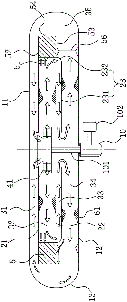
[0068] Such as figure 2 As shown, it is a schematic structural view of the heating furnace of the annular component in Embodiment 1 of the present invention. The heating furnace of the annular component in this embodiment includes a furnace body, a first centrifugal impeller 41 and a furnace for driving the first centrifugal impeller 41. Motor 10 is successively provided with a first flow-guiding partition 21, a second flow-guiding partition 22 and a third flow-guiding partition 23 from top to bottom in the body of heater, and on the top inner wall 11 of the body of heater, the first flow-guiding partition Between the plate 21, the second flow-guiding partition 22, the third flow-guiding partition 23 and the bottom inner wall 12 of the furnace body, the first airflow passage 31, the second airflow passage 32, and the third airflow passage are sequentially formed from top to bottom. Passage 33 and the 4th airflow passage 34, are provided with airflow heating accelerator in the...

Embodiment 2

[0083] Such as Figure 5 As shown, it is a schematic structural view of the heating furnace of the ring-shaped component in Embodiment 2 of the present invention. The difference between the heating furnace of the ring-shaped component in Embodiment 2 of the present invention and Embodiment 1 is that the third diversion plate 23 and the furnace body The second centrifugal impeller 42 is arranged between the bottom inner wall 12 of the bottom, and the gas flows into the air inlet of the second centrifugal impeller 42 after passing through the third air flow passage 33, and flows into the fourth airflow from the air outlet of the second centrifugal impeller 42 Channel 34.

[0084] After the gas hits the inner side wall of the ring part 5, the pressure decreases, and the second centrifugal impeller 42 boosts the air flow before the air flow flows to the fourth air flow passage 34, so that the speed at which the air flow hits the other surfaces of the ring part 5 is increased, ther...


PUM


Abstract

The invention provides a heating furnace of an annular component. A first guide partition plate, a second guide partition plate and a third guide partition plate are sequentially arranged inside a furnace body from top to bottom; a first airflow passage, a second airflow passage, a third airflow passage and a fourth airflow passage are sequentially formed between the top inner wall of the furnace body and the first guide partition plate, between the first guide partition plate and the second guide partition plate, between the second guide partition plate and the third guide partition plate and between the third guide partition plate and the bottom inner wall of the furnace body; airflow heating accelerators are arranged inside the second airflow passage and the fourth airflow passage; a first centrifugal impeller is arranged between the first guide partition plate and the second guide partition plate; a fifth airflow passage is formed by the upper and lower surfaces and the outer side wall of the annular component, and the top and bottom inner walls and the inner side wall of the furnace body; the first centrifugal impeller drives a gas to flow in circulating manner; the gas enters the second airflow passage from the air outlet of the first centrifugal impeller, hits against the inner side wall of the annular component after passing through the airflow heating accelerators, sequentially flows through the third airflow passage, the fourth airflow passage, the fifth airflow passage and the first airflow passage, and then enters the air inlet of the first centrifugal impeller. According to the heating furnace, the annular component can be specifically heated, and the energy consumption is relatively low.

Description

technical field [0001] The present invention relates to furnaces, and more particularly to furnaces for annular components. Background technique [0002] Some annular components need to be heated before mechanical assembly, and the typical annular components are bearings. In the field of wind turbine manufacturing, large-mass and large-size bearings need to be heated in a process called "shrink fitting". [0003] At present, the resistance heating furnace is generally used to heat the ring parts. The resistance heating furnace uses circulating hot air as the heat transfer medium. The thermal method transfers heat to the bearing. It adopts a composite heat transfer method that uses hot air as the heat transfer medium to conduct convective heat transfer on the bearing surface, supplemented by radiation heat transfer. Such as figure 1 As shown, it is a structural schematic diagram of an existing heating furnace. The furnace body of the existing heating furnace is divided int...

Claims


Application Information

Patent Timeline
Patent Type & Authority Applications(China)
IPC IPC(8): C21D9/40
Inventor 马盛骏刘承前
Owner XINJIANG GOLDWIND SCI & TECH
Why Eureka
Try Eureka