
APCVD furnace tube recover maintenance method

A furnace tube and organic matter technology, applied in the direction of gaseous chemical plating, metal material coating process, coating, etc., can solve the problems of high cost, time-consuming, low production efficiency, etc., achieve low cost, high efficiency, and prevent impact Effect

Active Publication Date: 2014-11-19
SEMICON MFG INT (SHANGHAI) CORP
View PDF6 Cites 3 Cited by
  • Summary
  • Abstract
  • Description
  • Claims
  • Application Information

AI Technical Summary

Problems solved by technology

However, this method is very time-consuming. The results of metal ions and organic substances need to be measured after each TLC and test run of the test wafer, and the position of the wafer on the wafer boat needs to be adjusted continuously for the thickness uniformity problem.
This results in low productivity and high costs

Method used


Image

  • APCVD furnace tube recover maintenance method
  • APCVD furnace tube recover maintenance method
  • APCVD furnace tube recover maintenance method

Examples


Embodiment 1

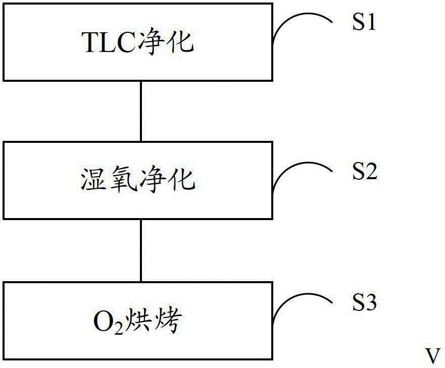
[0034] see image 3 , the present embodiment provides a method for repairing and maintaining an APCVD furnace tube, comprising the following steps:

[0035] Step 1, please refer to step S1, TLC purging (TLC purge), using N2, O2 combined with DCE (ie trans-dichloroethylene) to remove metal ions in the furnace tube and on the crystal boat located in the furnace tube. The temperature of the reaction is usually 1000-1150 degrees Celsius, and the thickness of the growth is about 1000 Angstroms (A). DCE is liquid at normal temperature. When using (i.e. when running a program), N2 enters the DCE storage bottle and then takes out the DCE to turn DCE into a gaseous state. Chloride ions from the DCE liquid enter the furnace tube in the form of a spray, and then react. Chloride ions mainly play a cleaning role, which can reduce the ion charge on the wafer, thereby reducing structural defects on the silicon surface. Since this step is a conventional technical means in the art, it will ...

Embodiment 2

[0045] see Figure 5 , the difference between the APCVD furnace tube recovery and maintenance method of this embodiment and the first embodiment is that: before step one, please refer to step S0, first perform O 2 Pre-baking to remove organic residues in the furnace tube and on the wafer boats in the furnace tube.

[0046] Preferably, in the above-mentioned APCVD furnace tube recovery maintenance method, O 2 During pre-baking, O 2 The gas flow rate is 10L ~ 20L / min, too high flow rate will affect the reaction effect, too high flow rate will affect the exhaust. The flow rate of 10L-20L / min combines the above two points to reach a better balance point. The reaction temperature is controlled at 1000°C-1150°C. A temperature that is too low will affect the reaction effect, and a temperature that is too high will affect the service life of the heater used to heat the temperature of the reaction chamber of the furnace tube. This temperature range better balances the above two fa...


PUM


Abstract

The invention discloses an APCVD furnace tube recover maintenance method. The method comprises the following steps: first, TLC purification is carried out, and metal ions located in a furnace tube and on a crystal boat in the furnace tube are cleared by utilization of oxygen and DCE; second, wet oxygen purification is carried out, and the DCE residuals located in the furnace tube and on the crystal boat in the furnace tube are removed; third, oxygen drying is carried out, and vapor and organic matters located in the furnace tube and on the crystal boat in the furnace tube are removed. Through addition of the wet oxygen purification step after the TLC purification step, the DCE residuals in the TLC step, especially chloride ion residuals in the DCE, can be removed effectively; through the oxygen drying step, vapor and organic matters in the furnace tube can be removed; therefore metal ions and organic matters can be removed, the affects of the DCE residuals and vapor to subsequent film thickness can be prevented effectively and the product yield rate is raised. Compared with the prior art, the method is advantaged by high efficiency and low cost.

Description

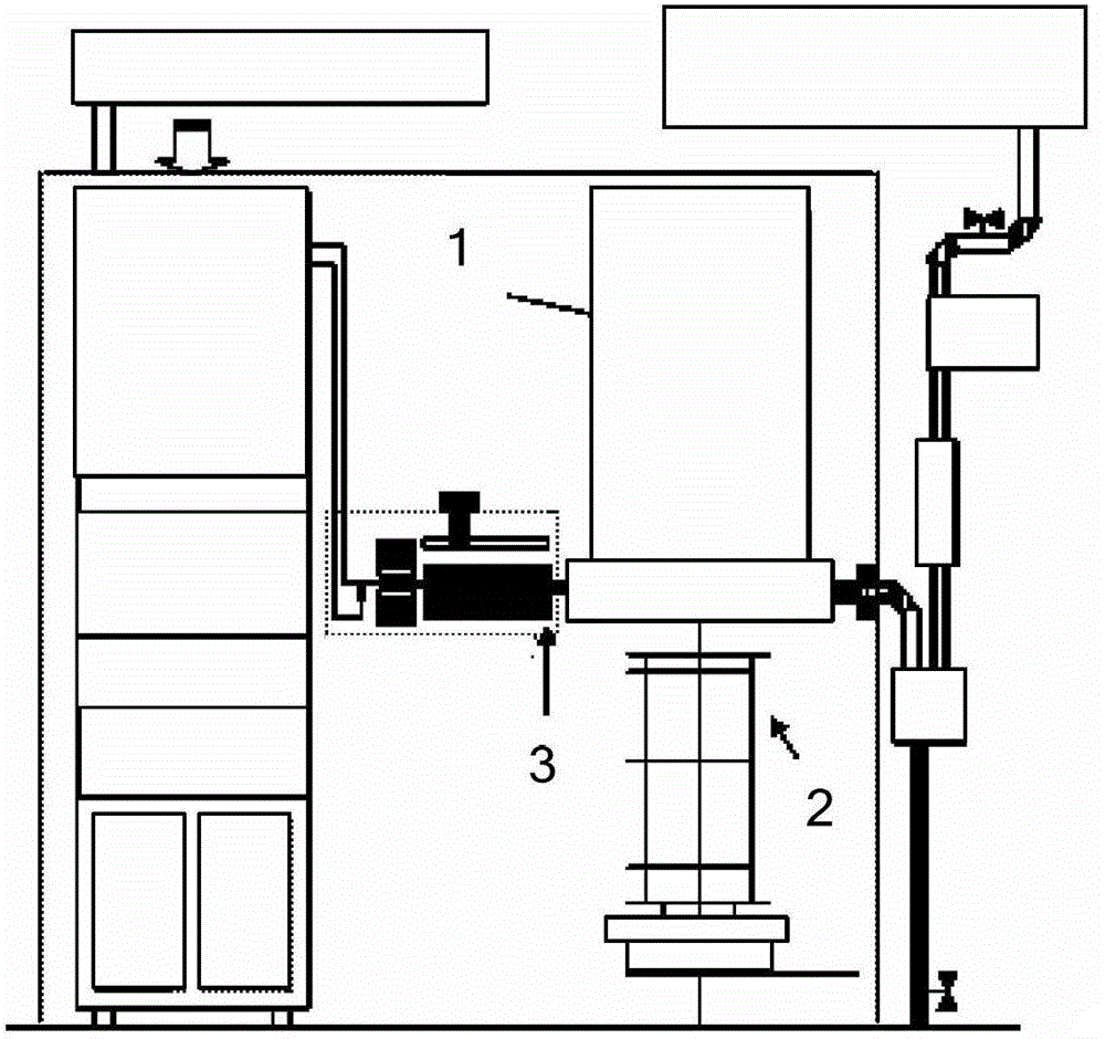
technical field [0001] The invention relates to the field of semiconductor manufacturing, in particular to an APCVD furnace tube recovery and maintenance method. Background technique [0002] In the semiconductor production process, for APCVD (atmospheric pressure chemical vapor deposition) furnace tubes, annual maintenance is performed every year, which is called APM (annual PM). In APM, the quartz,1, thermocouple, wafer boat2, ignition device3 and some quartz exhaust pipes are replaced, such as figure 1 as shown, figure 1 Shown is a schematic view of the structure of the APCVD furnace tube. [0003] Due to the placement of quartz, it is inevitable to encounter the problem of metal ion and organic pollution during the installation process. As a result, the metal ions and organic matter in the reaction chamber in the furnace tube after APM will exceed the standard. [0004] At present, the conventional practice in the industry for recovering the APCVD Furnace machine APM...

Claims


Application Information

Patent Timeline
Patent Type & Authority Applications(China)
IPC IPC(8): C23C16/44
Inventor 沈建飞
Owner SEMICON MFG INT (SHANGHAI) CORP
Learn More