
A rotating detonation gas turbine

A gas turbine and detonation technology, which is applied to gas turbine devices, deflagration combustion chambers, combustion chambers, etc., can solve the problems of easy flameout, complicated combustion control system, and narrow combustion stable area of ​​the combustion chamber, and achieves fast propagation speed and combustion efficiency. High, improve the effect of cycle thermal efficiency

Inactive Publication Date: 2015-10-28
XIAN THERMAL POWER RES INST CO LTD
View PDF5 Cites 0 Cited by
  • Summary
  • Abstract
  • Description
  • Claims
  • Application Information

AI Technical Summary

Problems solved by technology

[0005] The purpose of the present invention is to solve the problems existing in the existing ships and industrial gas turbines, such as the narrow combustion stable area of ​​the combustion chamber, easy flameout, complex combustion control system, and the need for frequent combustion adjustments, etc., and proposes a rotary detonation gas turbine

Method used


Image

  • A rotating detonation gas turbine
  • A rotating detonation gas turbine
  • A rotating detonation gas turbine

Examples


Embodiment Construction

[0027] The present invention will be described in further detail below in conjunction with the accompanying drawings.

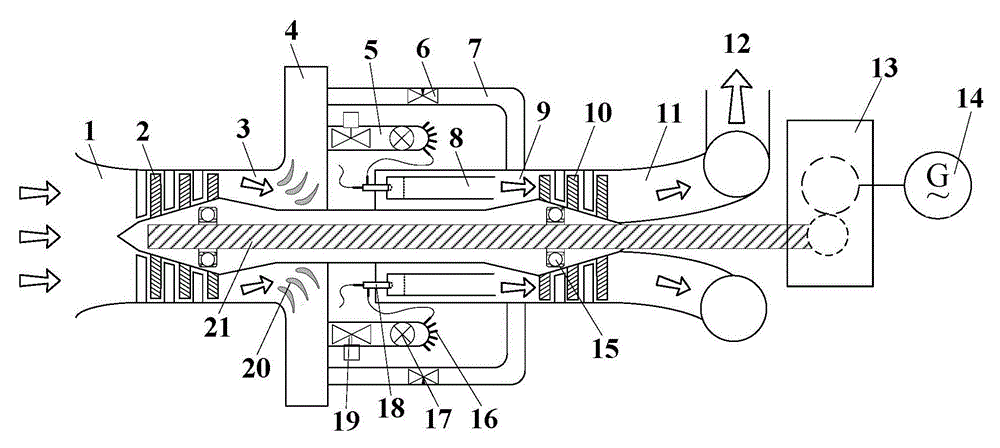
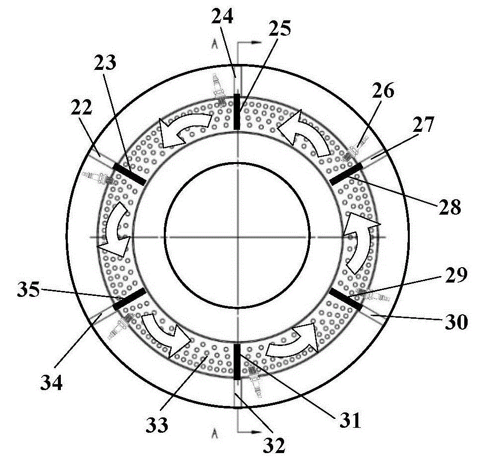
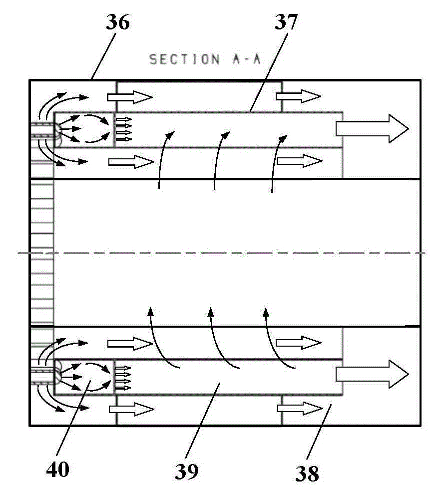
[0028]see figure 1 , a rotary detonation gas turbine of the present invention, comprising an air inlet 1, a diffuser section 3 and a gas storage chamber 4 sequentially connected from left to right, the compressor 2 is arranged downstream of the air inlet 1; the rotary detonation combustor 8 is located at the right end of the gas storage chamber 4, and the right end of the rotary detonation combustion chamber 8 is connected with a mixing chamber 9, a turbine 10 and an exhaust pipe 11 in sequence, and the left end surface of the rotary detonation combustion chamber 8 is provided with a plurality of nozzles in a ring at equal intervals 18. Six spark plugs 26 are evenly arranged in the circumferential direction of the rotary detonation combustion chamber 8; air passages 47 and fuel passages 48 are provided on a single nozzle, and the air storage chamber 4 passes ...


PUM


Abstract

The invention discloses a rotary knocking gas turbine. The rotary knocking gas turbine comprises a gas inlet passage, a diffusion section and a gas storage chamber which are connected in sequence from left to right, wherein a gas compressor is arranged at the downstream of the gas inlet passage; a rotary knocking combustion chamber is positioned at the right end of the gas storage chamber, the right end of the rotary knocking combustion chamber is connected with a mixing chamber, a turbine and an exhaust pipe in sequence, a plurality of nozzles are annularly arranged on the left end face of the rotary knocking combustion chamber at equal intervals, and six ignition plugs are uniformly arranged on the circumference of the rotary knocking combustion chamber; an air passage and a combustion passage are arranged on each nozzle, the gas storage chamber is communicated with the rotary knocking combustion chamber through a gas supply passage and the air passages of the nozzles, and the mixing chamber is communicated with the gas storage chamber through a gas escape bypass; a rotor is arranged between the gas compressor and the turbine, the gas compressor of a rotating component of the gas turbine and the turbine are connected with a casing of a static bearing component of the gas turbine through two bearings, and one end of the rotor is led out from the gas exhaust pipe. When the rotary knocking gas turbine is used, the leading-out end of the rotor is connected with a generator assembly through a speed changer.

Description

【Technical field】 [0001] The invention relates to a gas turbine, in particular to a rotating detonation gas turbine for ships and industries. 【Background technique】 [0002] Combustion is an indispensable key link in the release of fuel energy in gas turbines. There are many forms of combustion. According to the characteristics and methods of flame self-propagation, it can be divided into two types: slow combustion and detonation combustion. Slow-flame combustion is the acceleration of the reaction caused by the temperature rise of the unburned mixture through heat conduction (or the transfer of free atoms and free radicals to the unburned mixture due to thermal diffusion and thermal radiation to produce a chain reaction), thereby making the flame The leading edge continues to advance into the unburned mixture, and the flame surface of the slow-burning combustion is usually called a slow-burning wave. Due to the limitation of the temperature transfer mode of the slow-burning...

Claims


Application Information

Patent Timeline
Patent Type & Authority Patents(China)
IPC IPC(8): F02C7/00F23R7/00
Inventor 李晓丰肖俊峰王峰段静瑶
Owner XIAN THERMAL POWER RES INST CO LTD
Learn More