Gas pressure wave generator for regenerative type refrigerator

A technology of gas pressure and wave generator, which is applied in refrigerators, refrigeration and liquefaction, irreversible cycle compressors, etc. It can solve the problems of high consumption of high-purity gas, low compression efficiency, and difficulty in manufacturing compressors, etc., to achieve Effect of shortening processing cycle, improving compression efficiency, reducing gap sealing loss and shuttle loss

Inactive Publication Date: 2014-11-19
CHINA ELECTRONICS TECH GROUP CORP NO 16 INST
View PDF3 Cites 3 Cited by
  • Summary
  • Abstract
  • Description
  • Claims
  • Application Information

AI Technical Summary

Problems solved by technology

[0006] The object of the present invention is to provide a gas pressure wave generator for a regenerative refrigerator, which eliminates the need for compression pistons and compression cylinders, thereby eliminating the difficulty in manufacturing existing compressors, low compression efficiency, and high-purity gas consumption. Defects such as large quantity

Method used


Image

  • Gas pressure wave generator for regenerative type refrigerator
  • Gas pressure wave generator for regenerative type refrigerator

Examples


Embodiment 1

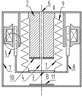
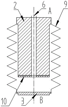
[0021] like Figure 1-Figure 2 A gas pressure wave generator for a regenerative refrigerator includes a motor 5 , a bellows assembly 1 and a fixed casing 7 . The motor 5 and the bellows assembly 1 are located in the fixed casing 7 . The motor 5 includes a stator part, a mover part and soft magnets. The bellows assembly 1 includes a bellows 9, a base 2 and a blind plate 3 fixedly connected to both ends of the bellows 9, respectively. The base body 2 is located in the bellows 9, and the base body 2 is provided with an exhaust port 6. The base body 2 , the blind plate 3 and the inner wall of the bellows 9 form a compression chamber 4 . One end of the bellows 9 fixed to the base body 2 is fixedly connected with the stator part through the fixed shell 7; The bellows 9 and the fixed end of the mover part reciprocate along the axial direction of the bellows 9 under the drive of the mover part, thereby driving the gas volume in the compression chamber 4 to change periodically, so ...

Embodiment 2

[0026] The motor 5 is a rotary motor, and the connecting frame 8 is a crank linkage mechanism. Through the crank linkage mechanism, the rotation angle of the rotary motor is converted into a linear displacement. Furthermore, end B of the corrugated tube 9 is driven to reciprocate along the axial direction of the corrugated tube 9 by the mover part of the motor 5 .

[0027] Others are with embodiment 1.

[0028] Concrete work process of the present invention is:

[0029] (1) Connect a three-way valve at the exhaust port 6 of the base body 2, so that the pressure wave generator of the one-way valve is inside the pressure wave generator of the two-way valve, and the three-way valve evacuates the pump. The gas pressure wave load can be a Stirling expander or a pulse tube refrigerator, and the gas filled in the refrigerator is high-purity helium.

[0030] (2) First open the one-way valve and the three-way valve, close the two-way valve, and evacuate and inflate the inside of the...


PUM


Abstract

The invention relates to a gas pressure wave generator for a regenerative type refrigerator. The gas pressure wave generator comprises motors, a corrugated pipe component and a fixed housing. The motors and the corrugated pipe component are arranged in the fixed housing. The motors comprise stator components, mover components and soft magnets. The corrugated pipe component comprises a corrugated pipe, a base and a blind plate. The base and the blind plate are fixedly connected with two ends of the corrugated pipe respectively. The base is arranged in the corrugated pipe and provided with an air exhausting outlet. The base, the blind plate and the inner wall of the corrugated pipe are combined to form a sealed compressing chamber. One end, fixed to the base, of the corrugated pipe is fixedly connected with the stator components, and one end, fixed to the blind plate, of the corrugated pipe is fixedly connected with the mover components. The end, fixed with the mover components, of the corrugated pipe is driven by the mover components to do reciprocating motion along the axial direction of the corrugated pipe, allowing pressure surge to occur to the filled gas. According to the technical scheme, the gas pressure wave generator is free of a compressing piston and a compressing cylinder and overcomes the defects of difficult production, low compressing efficiency and requirement on high quantity of the gas of the conventional compressor.

Description

technical field [0001] The invention relates to the technical field of regenerative refrigerators, in particular to a gas pressure wave generator for regenerative refrigerators. [0002] Background technique [0003] At present, in the regenerative cryogenic refrigerators that have been applied in engineering and are under development, a compressor with a piston and cylinder structure is used as a gas pressure wave generator, and the piston is driven by a motor to reciprocate in the cylinder to form a pressure wave. [0004] The motor in the compressor is used as the driving source to drive the compression piston to reciprocate in the compression cylinder, and generate a pressure wave with a certain pressure ratio through the exhaust port. The compressor with this structure has the following disadvantages: First, under the condition of no oil lubrication, the seal between the piston and the cylinder can only ensure the relative seal in the reciprocating process through a sm...

Claims


Application Information

Patent Timeline
Patent Type & Authority Applications(China)
IPC IPC(8): F25B1/00
Inventor 朱魁章杨坤
Owner CHINA ELECTRONICS TECH GROUP CORP NO 16 INST
Why Eureka
Try Eureka