
Probe self-damping method applied to fast scanning atomic force microscopy

An atomic force microscope and fast scanning technology, applied in scanning probe technology, scanning probe microscopy, measuring devices, etc., can solve the problems of complex focusing optical path, difficulty in applying fast scanning atomic force microscope, low first resonance frequency, etc. Achieve the advantage of high efficiency, the advantage of realization feasibility, the effect of low control voltage

Inactive Publication Date: 2014-11-19
INST OF ELECTRICAL ENG CHINESE ACAD OF SCI
View PDF3 Cites 9 Cited by
  • Summary
  • Abstract
  • Description
  • Claims
  • Application Information

AI Technical Summary

Problems solved by technology

[0005] The purpose of the present invention is to overcome the shortcomings of the prior art: due to the low first resonance frequency of the atomic force microscope (AFM) probe, although the first resonance frequency of the special tiny AFM probe is high, the focusing optical path is complicated, which makes it difficult to apply For fast scanning atomic force microscopy, a probe self-vibration reduction method suitable for fast scanning atomic force microscopy is proposed

Method used


Image

  • Probe self-damping method applied to fast scanning atomic force microscopy
  • Probe self-damping method applied to fast scanning atomic force microscopy
  • Probe self-damping method applied to fast scanning atomic force microscopy

Examples


Embodiment Construction

[0030] The present invention will be further described below in conjunction with the accompanying drawings and specific embodiments.

[0031] The steps of the inventive method are as follows:

[0032] 1) Processing ZnO thin films on atomic force microscope probes;

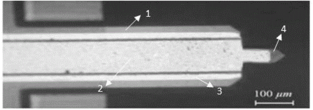
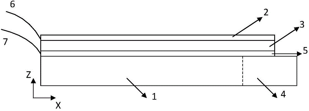
[0033] The top layer of Ti / Au alloy film 2, the middle layer of ZnO film 3, and the bottom layer of Ti / Au alloy film 4 are processed to the back of the silicon nitride probe 1 of the atomic force microscope in a sandwich structure by dry etching. figure 2 Shown is the image of the silicon nitride probe 1 under the electron microscope after the film structure has been processed, and its cross-sectional view is shown in image 3 As shown, the thickness of the top layer Ti / Au alloy film 2 and the bottom layer Ti / Au alloy film 4 are both about 0.2um, and the thickness of the ZnO thin film 3 is about 2um. The positive electrode 6 and the negative electrode 7 are respectively drawn from the top layer Ti / Au alloy film ...


PUM


Abstract

Provided is a probe self-damping method applied to fast scanning atomic force microscopy. According to the method, a ZnO film is machined on the back of a probe of an atomic force microscope by a dry etching method, and adjustable external damping is introduced to the probe by controlling the ZnO film to generate stress based on the inverse piezoelectric effect of the ZnO film so as to adjust the elastic coefficient of the probe and improve the first oscillation frequency of the prob. Thus, the probe is enabled to be applied to fast scanning atomic force microscopy, and self-excited oscillation of the probe in the process of fast scanning is eliminated.

Description

technical field [0001] The invention relates to a probe self-vibration reduction method applied to a fast scanning atomic force microscope. Background technique [0002] Atomic Force Microscopy (AFM, Atomic Force Microscopy) uses a piezoelectric scanner to drive the relative scanning motion between the probe and the sample in the horizontal plane (X, Y) direction. The technology detects the bending degree of the probe, so as to realize the perception of the surface topography of the scanned sample by AFM and the characterization of the interaction force with the probe. In order to prevent excessive interaction between the needle tip and the sample during the scanning process, thereby damaging the needle tip or the sample, the AFM generally turns on the feedback control of the piezoelectric scanner in the Z direction during the scanning process, and controls the piezoelectric scanner in the Z direction by detecting the bending degree of the probe. The scanner retracts to mai...

Claims


Application Information

Patent Timeline
Patent Type & Authority Applications(China)
IPC IPC(8): G01Q60/24G01Q60/38
Inventor 陈代谢殷伯华韩立刘俊标林云生初明璋
Owner INST OF ELECTRICAL ENG CHINESE ACAD OF SCI
Learn More