
A plastic window hole milling process based on a hole milling manipulator, and equipment

A manipulator and hole milling technology, applied in milling machine equipment, metal processing equipment, milling machine equipment details, etc., can solve the problems of low processing efficiency, low degree of automation, poor consistency of finished products, etc., achieve automatic processing, reduce the degree of manual participation, The effect of improving machining accuracy and machining consistency

Active Publication Date: 2014-11-26
UNIV OF JINAN
View PDF5 Cites 2 Cited by
  • Summary
  • Abstract
  • Description
  • Claims
  • Application Information

AI Technical Summary

Problems solved by technology

The process is cumbersome to operate, and the current degree of automation is not high or even completely manual operation, which has the problems of high labor intensity, low processing efficiency, and poor consistency of finished products.

Method used


Image

  • A plastic window hole milling process based on a hole milling manipulator, and equipment
  • A plastic window hole milling process based on a hole milling manipulator, and equipment

Examples


Embodiment 1

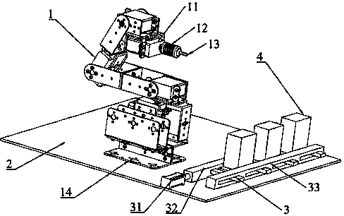
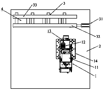
[0031] Such as figure 1 , figure 2 As shown, the plastic window milling process and equipment based on the milling manipulator, its structure includes: manipulator 1, servo motor 11, electric spindle 12, milling cutter 13, bracket 14, base 2, profile fixture 3, cylinder 31, sliding Splint 32, fixed splint 33; the manipulator 1 is fixed on the base 2 through the bracket 14, the manipulator 1 is driven by the servo motor 11, the end of the manipulator 1 is equipped with an electric spindle 12, and the electric spindle 12 drives the milling cutter 13 to rotate, sliding the splint 32 Installed on the base 2 with the fixed splint 33, the side of the sliding splint 32 and the fixed splint 33 are provided with a transverse strip structure, the fixed splint 33 is provided with a square groove along the length direction, and the transverse strip structure on the side of the sliding splint 32 passes through Through the square groove of the fixed splint 33, the cylinder 31 is located a...

Embodiment 2

[0033] The plastic window milling process and equipment based on the milling robot includes the following steps:

[0034] (1) The profile 4 to be processed is placed between the sliding splint 32 and the strip structure on the side of the fixed splint 33 .

[0035] (2) Start the cylinder 31, the front end of the piston rod of the cylinder 31 pushes the sliding splint 32, and the sliding splint 32 moves until the profile 4 is clamped by the strip structure on the side.

[0036] (3) Start the electric spindle 12 of the manipulator 1, and the electric spindle 12 drives the milling cutter 13 to rotate at a preset speed.

[0037] (4) Start the servo motor 11 of the manipulator 1, and the manipulator 1 completes the preset action under the drive of the servo motor 11, and completes the hole machining process on the profile 4 by means of the milling cutter 13.

[0038] (5) After the machining of the upper hole of the profile 4 is completed, the manipulator 1 returns to its position,...


PUM


Abstract

A plastic window hole milling process based on a hole milling manipulator and equipment are disclosed. The equipment comprises the manipulator, a servo motor, an electric spindle, a milling cutter, a support, a pedestal, section bar clamps, an air cylinder, a sliding clamping plate and a fixed clamping plate. The manipulator is driven by the servo motor. The tail end of the manipulator is provided with the electric spindle. The electric spindle drives the milling cutter to rotate. The sliding clamping plate and the fixed clamping plate are installed on the pedestal. Sides of the sliding clamping plate and the fixed sliding plate are provided with transversal bar mechanisms. The fixed clamping plate is provided with a square groove along the length direction. The transversal bar mechanisms at a side of the sliding clamping plate pass through the square groove of the fixed clamping plate. The air cylinder is disposed at the top of the sliding clamping plate. A piston rod of the air cylinder is connected to the top end of the sliding clamping plate by welding. Section bars are disposed among the transversal bar mechanisms of the sliding clamping plate and the fixed sliding plate. According to the process and the equipment, the automatic manipulator is utilized to drive the milling cutter to achieve the hole machining step of the section bars, thus achieving automatic machining, reducing the degree of participation of manual work, and improving the machining precision and machining consistency.

Description

technical field [0001] The invention relates to a plastic window milling process and equipment based on a milling manipulator, in particular to the field of plastic window automatic processing equipment. Background technique [0002] Plastic steel doors and windows are made of polyvinyl chloride (PVC) resin as the main raw material, plus a certain proportion of additives such as stabilizers, modifiers, colorants and ultraviolet absorbers, and are processed into profiles by extrusion, and then cut, welded, etc. It is processed into door and window frames and fans by means of different methods, and then equipped with accessories such as sealing strips, tops and hardware to make doors and windows. In order to increase the rigidity of the plastic profile, a steel lining reinforcement is added to the cavity of the profile, so it is called a plastic steel door, which can be roughly divided into the following categories: outward opening window, inner inverted window, inner opening ...

Claims


Application Information

Patent Timeline
IPC IPC(8): B23C3/00
Inventor 鲁帅帅昃向博吴长忠田田张孟杰栾富钰
Owner UNIV OF JINAN
Learn More