
Garbage incineration disposal device

A technology for processing equipment and garbage, applied in incinerators, combustion methods, combustion types, etc., can solve problems such as insufficiency, coking, and imperfection, and achieve the effects of improving incineration treatment quality, high interception effect, and improving utilization rate.

Active Publication Date: 2014-11-26
SHE COUNTY LVYUAN ENVIRONMENTAL PROTECTION EQUIP CO LTD
View PDF4 Cites 24 Cited by
  • Summary
  • Abstract
  • Description
  • Claims
  • Application Information

AI Technical Summary

Problems solved by technology

[0004] At present, the mainstream garbage harmless treatment device scheme is: including incinerator, flue gas control gate, flue gas turbulent flow channel, water mist dedusting pool, flue gas surrounding channel, induced draft fan, flue exhaust channel, water storage tank, etc. The feeding port is set on the top of the furnace, and the upper and lower flues are chambers surrounding the outer wall of the furnace. According to the characteristics of the physical components of its patented technology, after opening the slag cleaning door, two equal-velocity but not-isothermal parallel flow fields are in contact with each other in the combustion chamber. , the furnace temperature will quickly drop from a higher value to a lower value, and it is difficult to solve the problem of steady-state temperature in the center of the furnace, and it is impossible to promote the full combustion of garbage in the combustion chamber. In addition, the flue gas and the high-pressure spray water are in contact with each other, and the treatment method is not compatible with the physical and chemical characteristics, and the effect of dust removal and desulfurization is not obvious.
[0005] The patented technology with Chinese patent number 200810024382.6 discloses a patented technology of "garbage incineration treatment device and its treatment method". , harmless treatment of garbage, the flue gas treatment system consists of flow rate control components, turbulent flue gas duct, high-pressure spray dust removal pool, activated carbon adsorption chamber, induced draft fan and flue gas drying chamber, the furnace of this patent technology, The oxygen-increasing tube installed in the center of the furnace can only increase oxygen instantaneously. Because the normal-temperature air sent into the furnace lacks heat production due to the excessively fast conduction velocity, during the combustion process, a large amount of coking will occur in the center of the furnace. The air required for waste incineration cannot be supplied normally, which affects the quality of incineration and the increase and stability of the furnace center temperature. In addition, the high-pressure spray dust removal of the flue gas treatment system also adopts the homeopathic spray method, and the flue gas that receives high-pressure spray The temperature of the gas is as high as 800 ° C, and the expansion coefficient of the gas generated by contact with high-pressure spray water is as high as 3 times. The effect of dust removal and desulfurization can not meet the ideal conditions, and there is no matching for the unit components of the entire flue gas treatment. The intercepting component of particulate matter <0.5μm, that is to say, there is no necessary material basis for further conditioning of the discharged flue gas
[0006] Based on the analysis of the above two patented technologies, in addition to the above-mentioned unreasonable measures, there is also the effective use of heat energy emitted by the furnace body and high-temperature flue gas. The phenomenon of complete combustion and incomplete combustion of garbage caused by insufficient air and excess air is present throughout the operation. In the process, it is generated in turn, and the thermal balance of the combustion chamber cannot be guaranteed, so that harmful gases are easily generated, etc.
Carefully analyzing the entire processing system, there are still technical flaws, not very perfect

Method used


Image

  • Garbage incineration disposal device
  • Garbage incineration disposal device
  • Garbage incineration disposal device

Examples


Embodiment Construction

[0041] The present invention will be further described below in conjunction with drawings and embodiments.

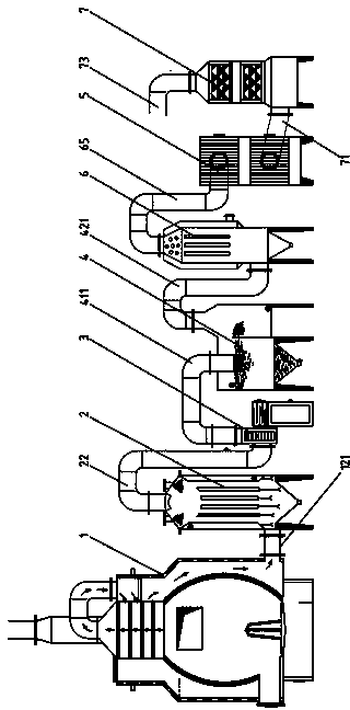
[0042] Such as figure 1 As shown, the present invention includes an incinerator 1, a quenching type high-pressure spray dedusting device 2, an induced draft fan 3, a flue gas melting water exchange treatment device 4, a flue gas treatment condenser 6, a combined sticky dust collector 5, and activated carbon Adsorption chamber 7, these components are connected one by one in the above order;

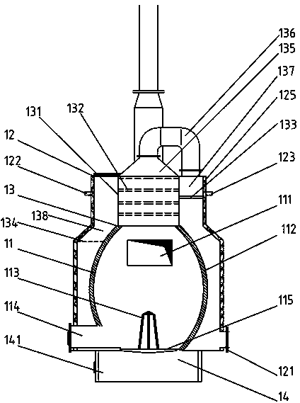
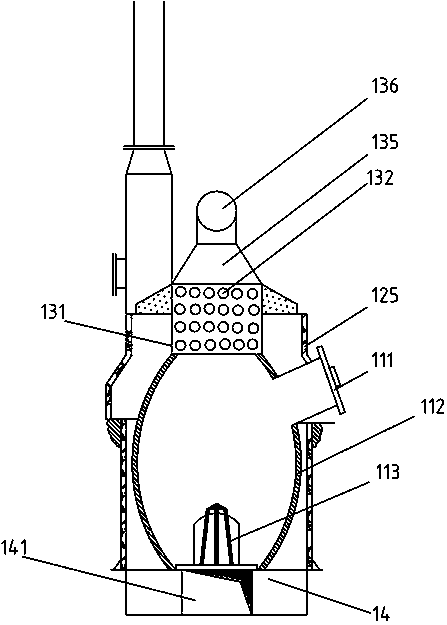
[0043] Such as figure 2 , image 3 As shown, the incinerator 1 includes a body of furnace 12, a furnace combustion chamber 11, a second combustion chamber 13, and a body of furnace base 14. In the middle and upper part, the second combustion chamber 13 is also connected with the upper end of the furnace combustion chamber 11, the furnace body base 14 is arranged on the bottom surface of the furnace body 12, and the furnace body base 14 is also connected with the furnace combusti...


PUM


Abstract

The invention discloses a garbage incineration disposal device which comprises an incinerator, a shock cooling type high-pressure spraying dust collection device, an induced draft fan, a smoke and melt water exchange treatment device, a smoke treatment condenser, a winding plate combination ash-sticking dust remover and an activated carbon adsorption chamber, wherein the incinerator, the shock cooling type high-pressure spraying dust collection device, the induced draft fan, the smoke and melt water exchange treatment device, the smoke treatment condenser, the winding plate combination ash-sticking dust remover and the activated carbon adsorption chamber are sequentially connected. The incinerator comprises an incinerator body, a hearth combustor, two combustors and an incinerator body base. The shock cooling type high-pressure spraying dust collection device comprises a spraying case, a smoke inlet pipe joint, a spraying water gathering hopper and a smoke outlet pipe joint. The smoke and melt water exchange treatment device comprises a smoke and melted water exchange treatment action tank, a water and smoke passing tank and an overflow gap water line control sideboard. The smoke treatment condenser comprises a condenser case, a smoke outlet pipe joint and a second smoke inlet pipe joint. The winding plate combination ash-sticking dust remover comprises an upper dust remover body and a lower dust remover body. The activated carbon adsorption chamber comprises an adsorption chamber case, a third smoke outlet pipe joint and a third smoke inlet pipe joint. The device saves energy, is environmentally friendly, generation of dioxin can be effectively restrained, garbage is combusted fully, and the maintenance cost is low.

Description

technical field [0001] The invention relates to an incineration treatment device for garbage, in particular to a harmless incineration treatment device for domestic garbage, which belongs to the technical field of domestic garbage treatment equipment. Background technique [0002] In the technical field of environmental pollution control and garbage disposal, the most practical and reliable method is to incinerate first and then landfill in the face of huge domestic garbage pollution sources, because the volume of garbage after incineration is only 1 / 5 of the original, and the weight is the original 1 / 15 of that can effectively reduce capacity. The premise of incinerating waste is to do a good job in waste reduction and waste classification. [0003] Incineration of domestic waste, and at the same time, the flue gas after waste incineration is effectively conditioned and discharged to high altitudes, that is to say, it is one of the important means of environmental governan...

Claims


Application Information

Patent Timeline
IPC IPC(8): F23G5/16F23G5/46F23J15/04
Inventor 张继宁潘慧敏
Owner SHE COUNTY LVYUAN ENVIRONMENTAL PROTECTION EQUIP CO LTD
Learn More