
Micro-structure surface global lighting drawing method based on direction light radiation intensity

A global illumination and microstructure technology, applied in 3D image processing, image data processing, instruments, etc., can solve problems such as inability to process and non-unique objects contained

Active Publication Date: 2014-11-26
BEIHANG UNIV
View PDF0 Cites 14 Cited by
  • Summary
  • Abstract
  • Description
  • Claims
  • Application Information

AI Technical Summary

Problems solved by technology

[0009] To sum up, the microstructure lighting algorithm based on texture map and the microstructure lighting algorithm based on precomputation are lighting rendering algorithms for a single object or model. They can draw direct lighting or the lighting effect inside their own microstructure, but for relatively In complex scenes, the objects contained in the scene are not unique, and there will be indirect lighting effects between objects, which cannot be handled by the above algorithms

Method used


Image

  • Micro-structure surface global lighting drawing method based on direction light radiation intensity
  • Micro-structure surface global lighting drawing method based on direction light radiation intensity
  • Micro-structure surface global lighting drawing method based on direction light radiation intensity

Examples


Embodiment Construction

[0039] The present invention will be further described below in conjunction with the accompanying drawings and specific embodiments of the present invention.

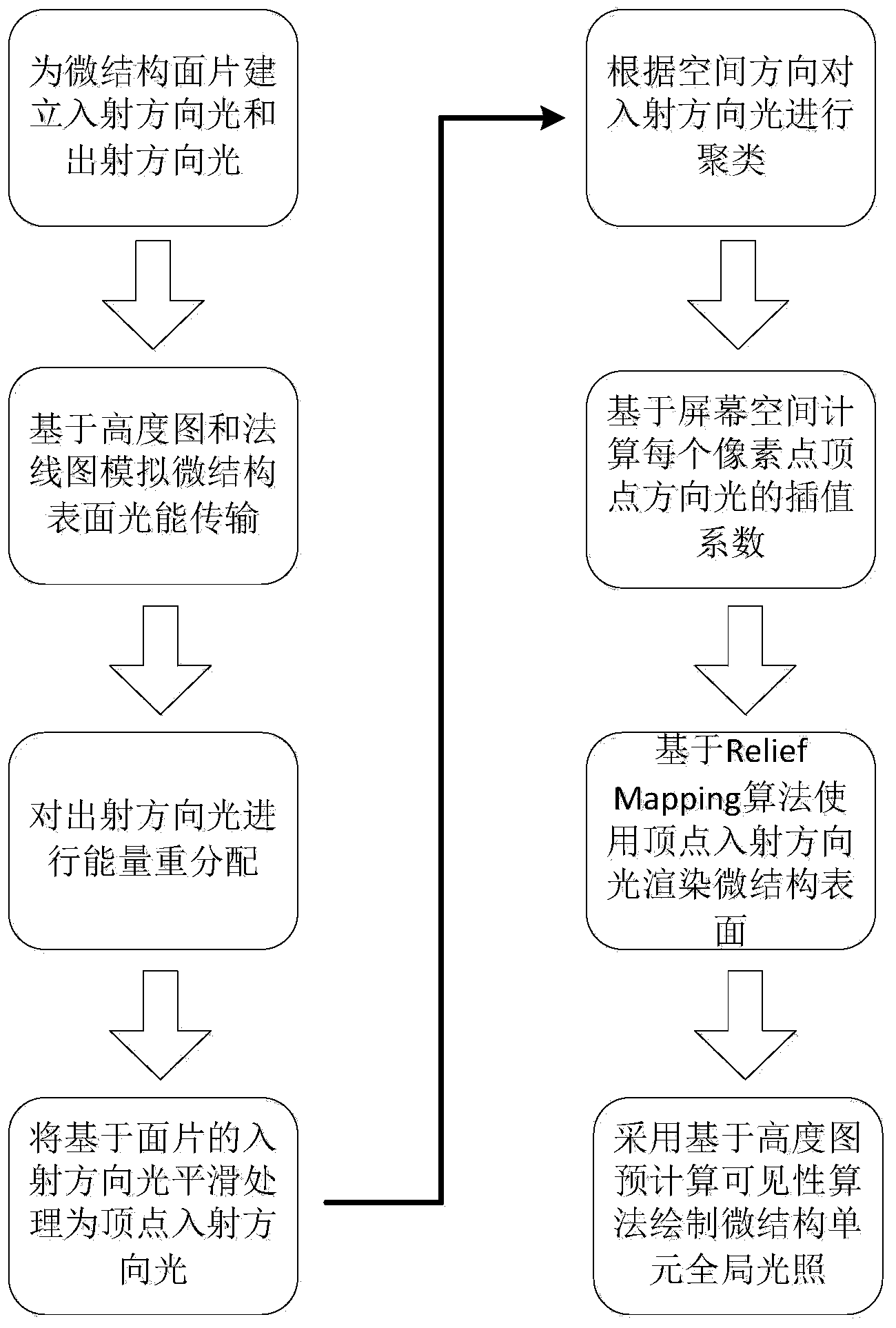
[0040] Such as figure 1 Shown, the present invention is concretely realized as follows:

[0041] Step (1) first find the tangent coordinate system for each patch of the scene, because the normal value obtained from the normal map is a fixed RGBA channel value, when the model view matrix changes, the normal will not change accordingly , which is not consistent with reality, the above problem can be solved when using tangent space. Calculate the tangant axis (T), binormal axis (B) and normal (N) axis according to the texture coordinates and normal of the triangular patch. These three vectors form a matrix and act on the texture normal to obtain the current model view. line value.

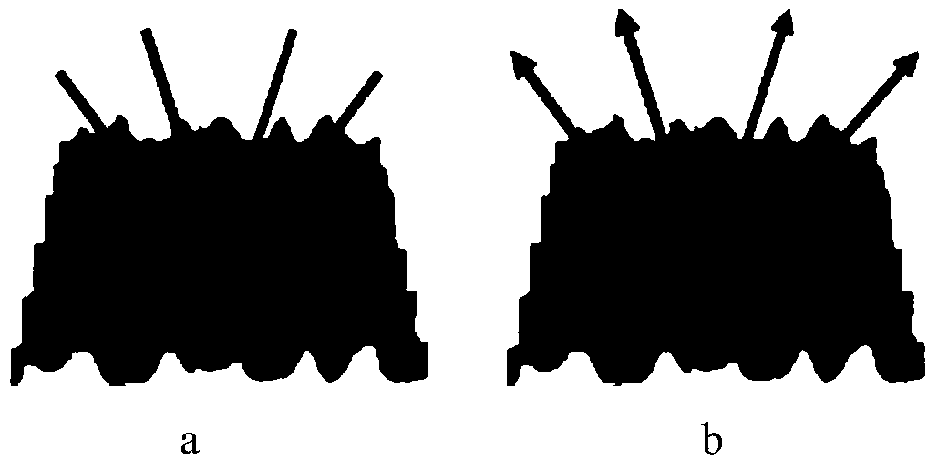
[0042] Create incoming and outgoing directional lights for patches (such as figure 2 , a is a schematic diagram of light in the incident ...


PUM


Abstract

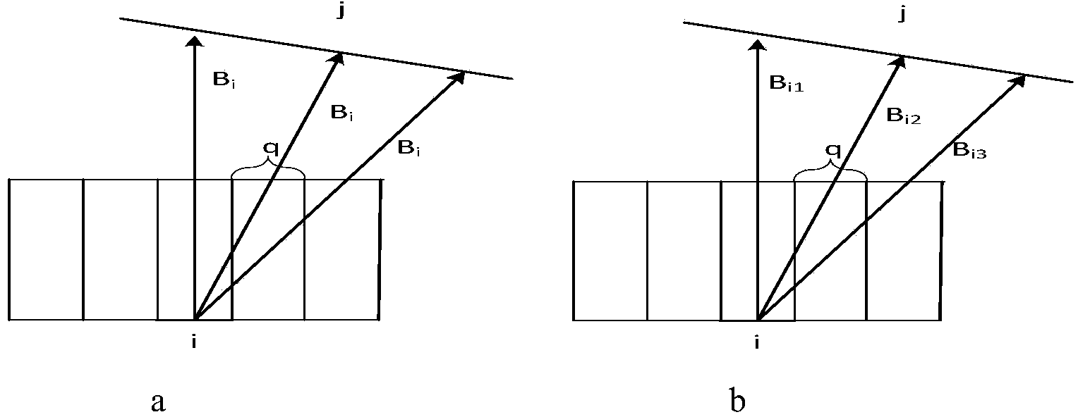
The invention discloses a micro-structure surface global lighting drawing method based on direction light radiation intensity. The method includes the following steps that a cluster of incidence direction light and exit direction light is established for a micro-structure surface, based on a height graph and a normal graph, a progressive radiation intensity algorithm is used for simulating the optical energy transmission of the scene of the micro-structure surface, energy redistribution is performed on the exit direction light, the incidence direction light is clustered after energy transmission is finished, smoothing processing from the facet incidence light to the top point incidence light is performed with the direction light roughly identical in space direction, based on screen space, the interpolation coefficient of the top point light in each pixel point is calculated, the scene is rendered through the clustered top point direction light via using the interpolation coefficient based on an Relief Mapping algorithm, and the global lighting effect among micro-structure units is drawn through a precomputation visibility algorithm based on the height graph.

Description

technical field [0001] The invention belongs to the technical field of realistic rendering and microstructure global illumination, and in particular relates to a global illumination drawing method of a microstructure surface based on radiance of directional light. Background technique [0002] In realistic rendering, the radiosity theory plays an important role in realistic rendering of physics. He regards the propagation of light as a kind of energy propagation, interprets light as discrete particle energy, and thus has a good effect. Based on the physical basis, any effect other than light diffraction and interference can be realistically realized through various improvement methods. [0003] Optical phenomena on the surface of objects are common natural phenomena in daily life. Its optical effect has a wide range of application requirements in the field of visual simulation. Their real-time realistic rendering is very important for improving the fidelity of virtual scen...

Claims


Application Information

Patent Timeline
Patent Type & Authority Applications(China)
IPC IPC(8): G06T15/00
Inventor 王莉莉彭通谢乃闻周士恒赵沁平
Owner BEIHANG UNIV
Learn More