Compressed air drying device based on vortex tube refrigeration technology and working method of compressed air drying device

A technology of compressed air and drying equipment, applied in the field of compressed air, which can solve the problems of complex structure of drying equipment, low working efficiency, waste of air potential energy, etc., to improve refrigeration efficiency and energy utilization, facilitate operation, and reduce outlet moisture content Effect

Inactive Publication Date: 2014-12-03
SOUTHEAST UNIV
View PDF3 Cites 13 Cited by
  • Summary
  • Abstract
  • Description
  • Claims
  • Application Information

AI Technical Summary

Problems solved by technology

[0004] However, in the prior art, for places that only need deep dry air at atmospheric pressure, the compressed air at the outlet of the high-pressure dehumidifier is directly throttled, resulting in a great waste of air potential energy. The drying device in the traditional technology has a complex structure and low work efficiency

Method used


Image

  • Compressed air drying device based on vortex tube refrigeration technology and working method of compressed air drying device

Examples


Embodiment 1

[0019] Embodiment 1 Compressed air drying device based on vortex tube refrigeration technology

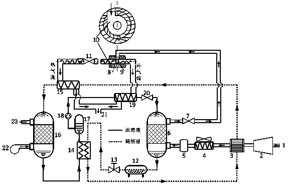
[0020] Such as figure 1 As shown, the compressed air drying device based on the vortex tube refrigeration technology includes an air inlet 1, an air compressor 2, a gas-liquid heat exchanger 3, an air cooler 4, a high-pressure gas storage tank 5, a high-pressure dehumidifier 6, and a first control valve 7. Nozzle 8, orifice plate 9, vortex chamber 10, second control valve 11, high pressure liquid storage tank 12, first throttle valve 13, intermediate heat exchanger 14, solution heater 15, normal pressure regenerator 16, normal pressure Pressure storage tank 17, high-pressure solution pump 18, solution cooler 19, third control valve 20, dry air outlet 21, blower fan 22 and regeneration air outlet 23; the above components respectively constitute the compressed air solution deep dehumidification drying assembly, high-pressure solution Dehumidification and atmospheric solution regener...

Embodiment 2

[0025] Embodiment 2 Working method of compressed air drying device based on vortex tube refrigeration technology

[0026] The working method of the compressed air high-efficiency dehumidification and drying device based on the vortex tube refrigeration technology mainly includes a compressed air drying process, a high-pressure solution dehumidification regeneration cycle process, and a vortex tube refrigeration enhanced solution dehumidification regeneration process.

[0027] The compressed air drying process is as follows: the wet air enters the air compressor 2 through the air inlet 1 to obtain compressed air after being compressed, the compressed air is cooled by the gas-liquid heat exchanger 3 and the air cooler 4, and then enters the high-pressure dehumidifier through the high-pressure gas storage tank 5 6. At the same time, the concentrated solution is pressurized and cooled by the high-pressure solution pump 18 and the solution cooler 19 in turn, and then enters the high...


PUM


Abstract

The invention discloses a compressed air drying device based on a vortex tube refrigeration technology, belonging to the technical field of air drying. The compressed air drying device comprises an air compressor, an air-liquid heat exchanger, an air cooler, a high-pressure air storage tank, a high-pressure dehumidifier, a first control valve, a nozzle, a pore plate, a vortex tube, a second control valve, a high-pressure liquid storage tank, a first throttling valve, an intermediate heat exchanger, a solution heater, a normal-pressure regenerator, a normal-pressure liquid storage tank, a high-pressure solution pump, a solution cooler, a third control valve and a dry air outlet. The invention further discloses a working method of the drying device. The drying device has the following beneficial effects of improving the energy utilization efficiency of the compressed air drying system, enhancing humidifying and regenerating effects, effectively reducing the moisture content of a compressed air outlet, and improving the refrigerating efficiency and the energy utilization rate of the vortex tube. The working method of the compressed air drying device based on the vortex tube regeneration technology is simple in steps and is energy-saving and environment-friendly.

Description

technical field [0001] The invention belongs to the technical field of air drying, in particular to a compressed air dryer based on vortex tube refrigeration technology. [0002] Gas drying device and its working method. Background technique [0003] Compressed air is the second largest power source next to electricity, and it is also a process gas source with multiple uses. Its application scope covers petroleum, chemical industry, metallurgy, electric power, machinery, electronics, food, medicine, national defense and other industries and departments. . As the wet air is compressed and condensed, it becomes wet-saturated air and entrains a large amount of liquid water droplets, which causes corrosion of equipment, pipes and valves, and freezes in winter to block the small holes in the pneumatic system, which adversely affects the production process and causes huge losses to the national economy. . In order to ensure the dry environment required in such low-humidity indu...

Claims


Application Information

Patent Timeline
Patent Type & Authority Applications(China)
IPC IPC(8): B01D53/26
Inventor 殷勇高郑宝军张小松
Owner SOUTHEAST UNIV
Why Eureka
Try Eureka