
A device and method for in-situ catalytic gasification of biomass to produce hydrogen-rich gas

A catalytic gasification and biomass technology, applied in the direction of granular/powdered fuel gasification, chemical recovery, etc., can solve difficult problems, difficult to control the air volume of secondary gasification agent, and large amount of heat carrier used

Inactive Publication Date: 2017-04-19
HUAZHONG NORMAL UNIV
View PDF9 Cites 0 Cited by
  • Summary
  • Abstract
  • Description
  • Claims
  • Application Information

AI Technical Summary

Problems solved by technology

Many people have carried out relevant research on tar in the process of biomass gasification, and developed some methods and devices for removing tar. For example, in a biomass composite gasification method and device (CN201713504U), the gasifier is divided into gas The upstream section of the gasifier, the crossflow section of the gasifier, and the downstream section of the gasifier are composed of three parts. In this method, the tar entrained in the gas is cracked at a high temperature by raising the temperature of the downstream section of the gasifier to 1000-1300°C. It takes a lot of energy to produce such a high temperature, so that a large amount of gas produced by biomass gasification is burned to maintain this temperature, and how to control the amount of oxygen in the gasification agent in the actual process is a difficult problem. On the one hand, it is difficult to achieve complete cracking of tar only by high temperature cracking
A gasification device and method for preparing hydrogen-rich synthesis gas from biomass (CN101880552A), in which under the action of a calcium-based heat carrier, the biomass is absorbed by a calcium-based absorbent under the action of part of the water vapor as a gasification medium CO in 2 In this method, how the calcium-based heat carrier circulates in the gasification chamber and the combustion chamber, and how to maintain the heat balance of the system when water vapor is used as the gasification medium, is difficult to control in the actual operation process. accomplish
In the method of solid heat carrier catalytic gasification of biomass hydrogen-rich gas (CN1277740C) patent, solid heat carrier is mainly used to provide the heat required for biomass gasification, because the amount of heat carrier used is large (1:1-8:1) As a result, the problem of stratified fluidization and inhomogeneous contact pyrolysis of the heat carrier and the biomass raw material due to the large density difference between the two
In addition, in the patent, the unreacted residual biomass charcoal is used to regenerate the catalyst, that is, CaCO 3 Decompose into CaO, and remove the carbon deposits on the catalyst. Since water vapor is added to the gasification system, how to ensure the heat balance in the gasification and regeneration system is the difficulty in the implementation of this patent, that is, how the air added from the bottom Reasonable distribution between the regeneration bed and the gasification bed. The heat provided by the residual biomass charcoal cannot meet the heat required for the thermal decomposition of the catalyst. How to operate and maintain the pressure balance of the entire circulation system is another difficulty in operation.
A biomass gasification catalytic cracking process and integrated gasification catalytic reactor patent (CN102807901A) puts the tar cracking catalyst in the upper section of the gasification reactor, although the energy required for the cracking process of tar does not need an external heating source , and the carbon deposits generated during the tar cracking process can be solved by adding a secondary gasification agent, but the amount of air in the secondary gasification agent is difficult to control. The invention patents a biomass in-situ catalytic gasification to produce hydrogen-rich The gas method was proposed under the above background. While overcoming the above problems, it is easy to operate and easy to control, and it better solves the problem of tar produced in the process of biomass gasification.

Method used


Image

  • A device and method for in-situ catalytic gasification of biomass to produce hydrogen-rich gas
  • A device and method for in-situ catalytic gasification of biomass to produce hydrogen-rich gas
  • A device and method for in-situ catalytic gasification of biomass to produce hydrogen-rich gas

Examples


Embodiment 1

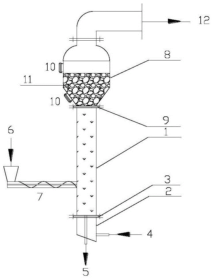
[0029]Biomass wood powder with a particle size of 5 mm and nickel catalyst mixture 6 with a particle size of 5.31 μm and 2% of the wood powder mass are fed into the lower fluidized section 1 of the biomass in-situ catalytic gasification reactor through a screw feeding device 7 , the gasification medium is air, which enters the equal-pressure air chamber 2 through the gasification agent inlet 4, and then enters the interior of the fluidization section 1 through the air distribution plate 3, and controls the feeding rate and the amount of the gasification medium so that the air-fuel ratio is Under the condition of 0.23, the oxidation-reduction reaction occurs in the biomass gasification section at 600°C-750°C, generating flammable gas and accompanied by the formation of tar, which undergoes in-situ catalytic cracking under the action of the catalyst to form small molecules Gas, hydrogen-rich combustible gas entrained with fly ash, as well as incompletely reacted biomass particles...

Embodiment 2

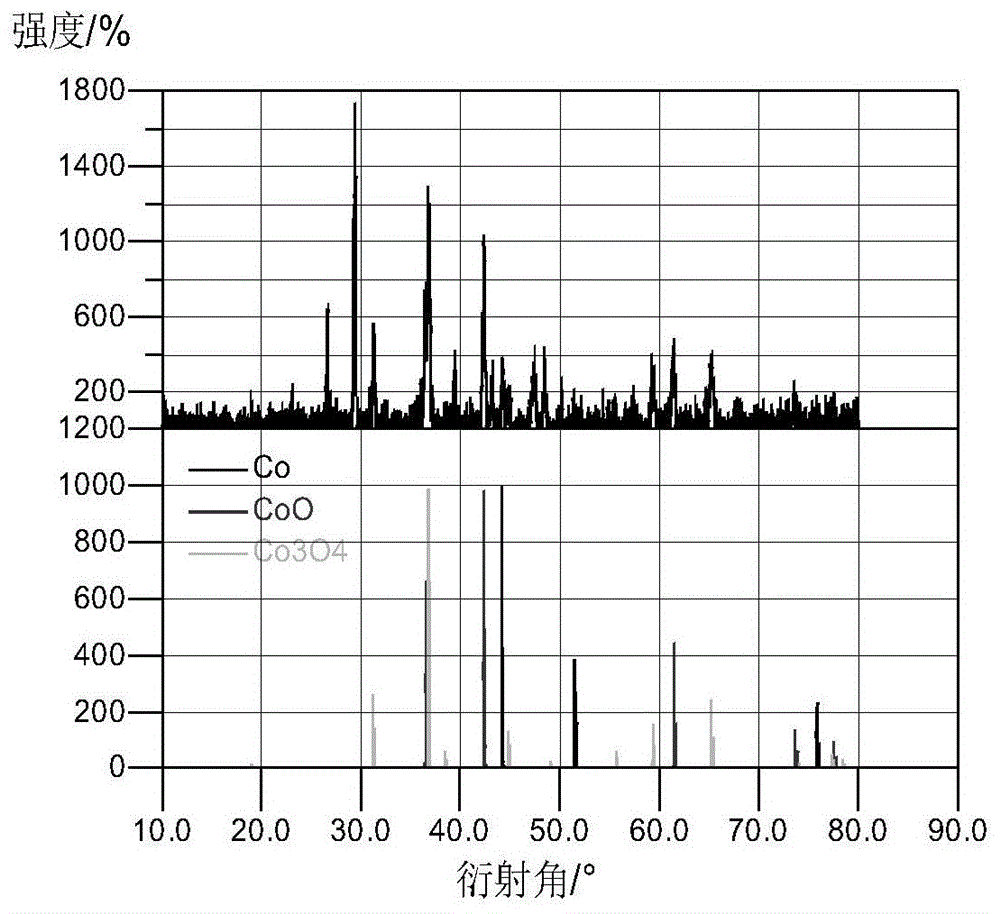
[0031] The 8mm biomass chaff and the cobalt catalyst 6 with 2% of the chaff mass and a particle size of 6 μm are fed into the lower fluidization section 1 of the biomass in-situ catalytic gasification reactor through the screw feeding device 7, and the air gasification medium passes through The gasification agent inlet 4 enters the equal pressure air chamber 2, and then enters the interior of the biomass fluidization gasification section 1 through the air distribution plate 3. By controlling the feeding rate and the amount of gasification medium added, the air-fuel ratio is 0.23, and the biomass In the material gasification section, oxidation-reduction reactions occur at 600°C-750°C, and flammable gases are produced, accompanied by the generation of tar. Under the action of the catalyst, the tar undergoes in-situ catalytic cracking to generate small molecule gas, which is hydrogen-rich and flammable. The gas entrains fly ash, as well as incompletely reacted carbon particles and...


PUM

PropertyMeasurementUnit
particle sizeaaaaaaaaaa
particle diameteraaaaaaaaaa

Abstract

The invention discloses a device and method for preparing hydrogen-enriched gas through in-situ catalytic gasification of biomasses. The method comprises the steps of uniformly adding a catalyst with catalytic cracking activity and a biomass raw material into a biomass gasification reactor according to a certain ratio; carrying out in-situ catalytic cracking on tar supervened in the biomass gasification process under the action of the catalyst to generate the hydrogen-enriched gas; discharging the catalyst playing a catalyzing role and biomass ash from the bottom of the reactor; separating the catalyst and the biomass ash; and then, recycling the catalyst. The catalytic cracking temperature of the tar is consistent with the biomass gasification temperature, and carbon deposits generated in the catalytic cracking process of the tar are removed through carrying out redox reaction in a gasification furnace, so that the catalytic activity is kept, the problem that the catalyst is rapidly deactivated by carbon deposition in the current biomass and tar catalytic cracking process is solved, the biomass gasification efficiency is increased, and the broad application prospect is provided for the development and utilization of biomass energy.

Description

technical field [0001] The invention relates to a device and method for in-situ catalytic gasification of biomass to produce hydrogen-rich gas, belonging to the technical field of biomass energy. Background technique [0002] Biomass gasification is one of the most promising methods for large-scale utilization of biomass energy, however, the tar produced during biomass gasification seriously hinders its large-scale application. For the tar produced in the process of biomass gasification, two methods are currently used to deal with the tar, one is to remove the tar after the gasification reactor by washing with water; the other is to use fixed bed catalysis at the rear of the gasification reactor Cracking removes tar. Water washing to remove tar produces a large amount of waste water and secondary pollution. Fixed-bed catalytic cracking removes tar, and the catalyst will be deactivated quickly due to carbon deposition in the process of tar cracking. Solving the carbon depos...

Claims


Application Information

Patent Timeline
Patent Type & Authority Patents(China)
IPC IPC(8): C10J3/56C10J3/54
CPCY02P20/584
Inventor 吴正舜姜晓敏彭乔吴云芬米铁陈汉平
Owner HUAZHONG NORMAL UNIV
Learn More