Light source device adapted to a direct-type backlight module and display device therewith

A technology of light source device and display module, which is applied in the direction of electric light source, lighting device, light source fixation, etc., can solve problems such as increasing the light emitting angle of light emitting diodes, reducing the life of light emitting diode elements, and increasing the working temperature of light emitting diodes, so as to prevent the working temperature Too high, increase heat dissipation efficiency, increase the effect of projected area

Inactive Publication Date: 2014-12-03
潘宇翔 +1
View PDF6 Cites 1 Cited by
  • Summary
  • Abstract
  • Description
  • Claims
  • Application Information

AI Technical Summary

Problems solved by technology

[0003] However, the above method of reducing the number of LEDs will reduce the light source density projected on the LCD panel, so that the LCD panel cannot obtain uniform brightness with the above-mentioned small number of LEDs. The light emitting angle of the diode is used to increase the projection area of ​​a single light-emitting diode on the LCD panel, which can improve the uniformity of light received by the LCD panel
In addition, the above-mentioned way of reducing the number of light-emitting diodes will reduce the light intensity projected on the liquid crystal display panel, so that the liquid crystal display panel cannot obtain sufficient brightness with the above-mentioned small number of light-emitting diodes. The driving current of the light-emitting diode is used to increase the luminous flux of a single light-emitting diode, but the above-mentioned method of increasing the driving current of the light-emitting diode will generate more heat and increase the operating temperature of the light-emitting diode, thereby reducing the life of the components of the light-emitting diode

Method used


Image

  • Light source device adapted to a direct-type backlight module and display device therewith
  • Light source device adapted to a direct-type backlight module and display device therewith
  • Light source device adapted to a direct-type backlight module and display device therewith

Examples


Embodiment Construction

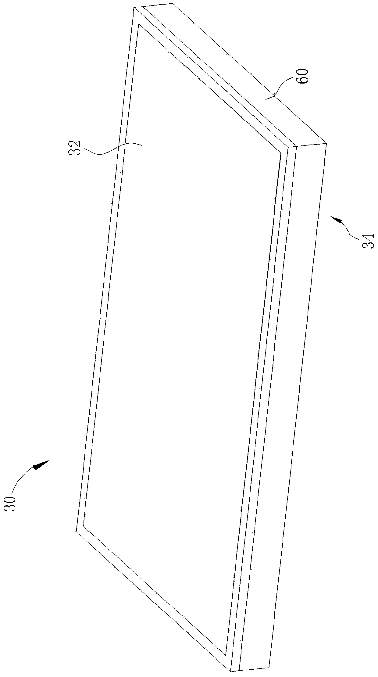
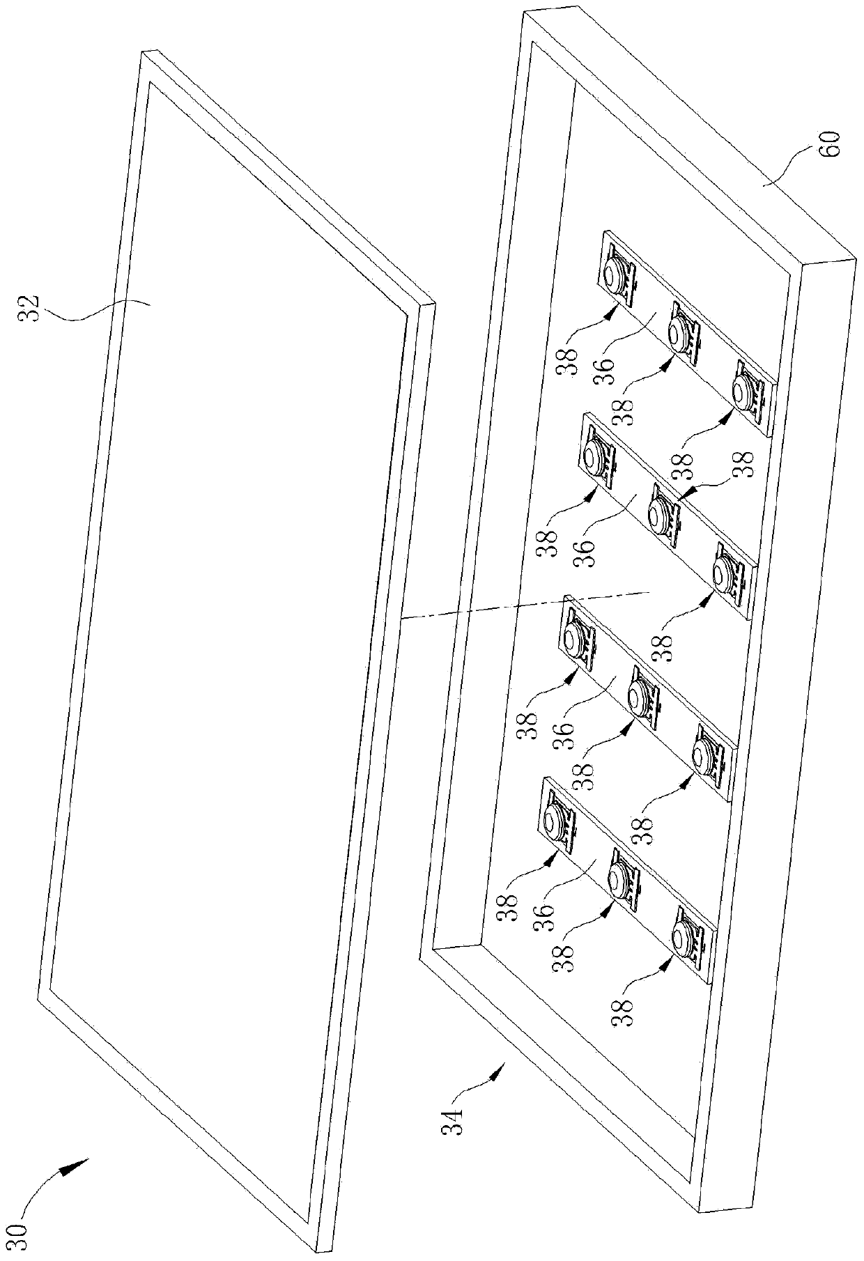
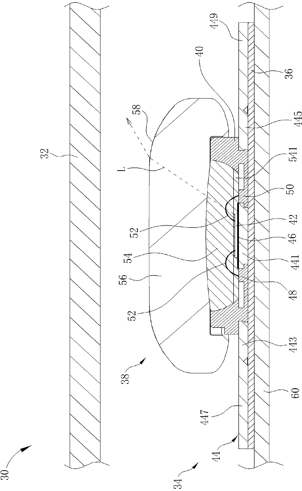
[0051] The directional terms mentioned in the following embodiments, such as: up, down, left, right, front or back, etc., are only directions referring to the attached drawings. Accordingly, the directional terms are used to illustrate and not to limit the invention. see Figure 1 to Figure 3 , figure 1 It is a schematic diagram of the appearance of a display 30 according to Embodiment 1 of the present invention, figure 2 It is an explosion schematic diagram of the display 30 according to the embodiment of the present invention, image 3 It is a partial cross-sectional schematic diagram of a display 30 according to an embodiment of the present invention. like Figure 1 to Figure 3 As shown, the display 30 includes a display module 32 and a direct-type backlight module 34 . The direct-type backlight module 34 is installed under the display module 32 and used to provide light to the display module 32 so that the display module 32 can display images normally. In this embodi...


PUM


Abstract

A light source device (38) includes a frame (40), at least one light emitting chip (42), a light transferring layer (54) and a lens layer (56). The at least one light emitting chip (42) is present within the frame (40) for emitting light. The light transferring layer (54) covers the at least one light emitting chip (42) and combines with the frame (40). The lens layer (56) is formed on the frame (40) and contacts and combines with the light transferring layer (54), such that the light emitted from the at least one light emitting chip (42) directly projects into the lens layer (56) after passing through the light transferring layer (54). The lens layer (56) has a light emitting surface (58) on the other face to the light transferring layer (54) for transferring the light emitted from the at least one light emitting chip (42) into a light shape after passing through the light transferring layer (54) and the lens layer (56).

Description

technical field [0001] The invention relates to a light source device and a display thereof, in particular to a light source device and a display thereof which have a large light output angle and can improve heat dissipation efficiency. Background technique [0002] Generally speaking, the main function of the backlight module of a liquid crystal display (LCD) panel is to provide a light source with sufficient brightness and uniform distribution for the LCD panel, so that the LCD panel can display images normally. Recently, due to the advantages of light emitting diodes (Light Emitting Diode, LED) with low energy consumption, long life and no need for warm-up time, etc., the backlight module equipped with light emitting diodes has gradually become a new light source for LCD panels, and the backlight module can be used according to The position of the light-emitting diode is divided into direct-type (direct-type) and edge-type (edge-type) two designs, of which the direct-type...

Claims


Application Information

Patent Timeline
Patent Type & Authority Applications(China)
IPC IPC(8): F21S8/00F21V29/00F21V19/00F21V17/10G02F1/13357
CPCH01L33/642G02F2001/133628G02F2001/133607G02F1/133603H01L33/58H01L33/56H01L2924/181H01L2224/48091H01L24/97G02F1/133628G02F1/133607H01L2924/00012H01L2924/00014
Inventor 潘宇翔詹子莹
Owner 潘宇翔
Why Eureka
Try Eureka